<?xml version="1.0" encoding="ISO-8859-1"?><article xmlns:mml="http://www.w3.org/1998/Math/MathML" xmlns:xlink="http://www.w3.org/1999/xlink" xmlns:xsi="http://www.w3.org/2001/XMLSchema-instance">
<front>
<journal-meta>
<journal-id>0254-0770</journal-id>
<journal-title><![CDATA[Revista Técnica de la Facultad de Ingeniería Universidad del Zulia]]></journal-title>
<abbrev-journal-title><![CDATA[Rev. Téc. Ing. Univ. Zulia]]></abbrev-journal-title>
<issn>0254-0770</issn>
<publisher>
<publisher-name><![CDATA[Facultad de Ingeniería, Universidad del Zulia]]></publisher-name>
</publisher>
</journal-meta>
<article-meta>
<article-id>S0254-07702009000300002</article-id>
<title-group>
<article-title xml:lang="en"><![CDATA[Assessment of the structural integrity of cracked cylindrical geometries applying the EVTUBAG program]]></article-title>
<article-title xml:lang="es"><![CDATA[Evaluación de la integridad estructural de geometrías cilíndricas agrietadas aplicando el programa EVTUBAG]]></article-title>
</title-group>
<contrib-group>
<contrib contrib-type="author">
<name>
<surname><![CDATA[Hernández Gómez]]></surname>
<given-names><![CDATA[Luis Héctor]]></given-names>
</name>
<xref ref-type="aff" rid="A01"/>
</contrib>
<contrib contrib-type="author">
<name>
<surname><![CDATA[Urriolagoitia Calderón]]></surname>
<given-names><![CDATA[Guilllermo]]></given-names>
</name>
<xref ref-type="aff" rid="A01"/>
</contrib>
<contrib contrib-type="author">
<name>
<surname><![CDATA[Urriolagoitia Sosa]]></surname>
<given-names><![CDATA[Guillermo]]></given-names>
</name>
<xref ref-type="aff" rid="A01"/>
</contrib>
<contrib contrib-type="author">
<name>
<surname><![CDATA[Sandoval Pineda]]></surname>
<given-names><![CDATA[Juan Manuel]]></given-names>
</name>
<xref ref-type="aff" rid="A02"/>
</contrib>
<contrib contrib-type="author">
<name>
<surname><![CDATA[Merchán Cruz]]></surname>
<given-names><![CDATA[Emmanuel Alejandro]]></given-names>
</name>
<xref ref-type="aff" rid="A02"/>
</contrib>
<contrib contrib-type="author">
<name>
<surname><![CDATA[Guardado García]]></surname>
<given-names><![CDATA[José Francisco]]></given-names>
</name>
<xref ref-type="aff" rid="A01"/>
</contrib>
</contrib-group>
<aff id="A01">
<institution><![CDATA[,Unidad Profesional Adolfo López Mateos  ]]></institution>
<addr-line><![CDATA[Zacatenco ]]></addr-line>
<country>México</country>
</aff>
<aff id="A02">
<institution><![CDATA[,Instituto Politécnico Nacional Escuela Superior de Ingeniería Mecánica y Eléctrica ]]></institution>
<addr-line><![CDATA[México D.F]]></addr-line>
<country>México</country>
</aff>
<pub-date pub-type="pub">
<day>00</day>
<month>12</month>
<year>2009</year>
</pub-date>
<pub-date pub-type="epub">
<day>00</day>
<month>12</month>
<year>2009</year>
</pub-date>
<volume>32</volume>
<numero>3</numero>
<fpage>190</fpage>
<lpage>199</lpage>
<copyright-statement/>
<copyright-year/>
<self-uri xlink:href="http://ve.scielo.org/scielo.php?script=sci_arttext&amp;pid=S0254-07702009000300002&amp;lng=en&amp;nrm=iso"></self-uri><self-uri xlink:href="http://ve.scielo.org/scielo.php?script=sci_abstract&amp;pid=S0254-07702009000300002&amp;lng=en&amp;nrm=iso"></self-uri><self-uri xlink:href="http://ve.scielo.org/scielo.php?script=sci_pdf&amp;pid=S0254-07702009000300002&amp;lng=en&amp;nrm=iso"></self-uri><abstract abstract-type="short" xml:lang="en"><p><![CDATA[In this paper, the assessment of the structural integrity of pressurized cylindrical components containing defects like cracks was performed, considering two types of failures. Brittle failure was evaluated considering Fracture Mechanics and ductile failure was calculated with a plastic analysis. For this purpose, three methods were used. Accordingly, the program EVTUBAG (evaluation of cracked pipe by its initials in Spanish) was written considering the methodologies proposed by Ruiz and Corran, ASME and Raju-Newman. This paper describes this program and relevant results are discussed.]]></p></abstract>
<abstract abstract-type="short" xml:lang="es"><p><![CDATA[En este trabajo, se realizó una evaluación de la integridad estructural de componentes cilíndricos agrietados sujetos a presión interna. Para este efecto, se consideraron dos tipos de falla. La frágil fue evaluada bajo criterios de Mecánica de la Fractura y la dúctil se calculó con análisis plástico. Para este efecto, se desarrollaron y aplicaron tres diferentes metodologías. Por lo que se implementó el programa EVTUBAG (Evaluación de Tubería Agrietada), en el cual se consideran tres procedimientos, propuestos por Ruiz y Corran, ASME y Raju-Newman. En este artículo se describe la aplicación de este programa y se analizan los resultados relevantes obtenidos.]]></p></abstract>
<kwd-group>
<kwd lng="en"><![CDATA[Longitudinal cracks]]></kwd>
<kwd lng="en"><![CDATA[circumferential cracks]]></kwd>
<kwd lng="en"><![CDATA[stress intensity factor]]></kwd>
<kwd lng="en"><![CDATA[cracked cylindrical vessel]]></kwd>
<kwd lng="en"><![CDATA[limit analysis]]></kwd>
<kwd lng="es"><![CDATA[Grietas longitudinales]]></kwd>
<kwd lng="es"><![CDATA[grietas circunferenciales]]></kwd>
<kwd lng="es"><![CDATA[factor de intensidad de esfuerzos]]></kwd>
<kwd lng="es"><![CDATA[recipiente cilíndrico agrietado]]></kwd>
<kwd lng="es"><![CDATA[análisis al límite]]></kwd>
</kwd-group>
</article-meta>
</front><body><![CDATA[  <BASEFONT SIZE="3"> <MULTICOL GUTTER="39" COLS="2">     <P ALIGN="center"><FONT COLOR="#1f1a17" FACE="Verdana"> <B>Assessment of the structural integrity of cracked cylindrical geometries  applying the EVTUBAG program</B></FONT></P> <font face="Verdana" size="2"></font>     <P ALIGN="center"><FONT COLOR="#1f1a17" SIZE="2" FACE="Verdana"> <B>Luis H&#233;ctor Hern&#225;ndez G&#243;mez</B><SUP><B>1</B></SUP><B>, Guilllermo Urriolagoitia Calder&#243;n</B><SUP><B>1</B></SUP><B>, Guillermo  Urriolagoitia Sosa</B><SUP><B>1</B></SUP><B>, Juan Manuel Sandoval Pineda</B><SUP><B>2</B></SUP><B>, Emmanuel Alejandro Merch&#225;n  Cruz</B><SUP><B>2</B></SUP><B> y Jos&#233; Francisco Guardado Garc&#237;a</B><SUP><B>1</B></SUP></FONT></P>     <P ALIGN="justify"><FONT COLOR="#1f1a17" FACE="Verdana" SIZE="2"><SUP>1</SUP>Unidad Profesional &#147;Adolfo L&#243;pez Mateos&#148; Zacatenco. Edificio 5, 2do. Piso,  Col. Lindavista, C. P. 07738.</FONT></P>     <P ALIGN="justify"><FONT COLOR="#1f1a17" FACE="Verdana" SIZE="2"><SUP>2</SUP>Unidad Azcapotzalco, Av. de las Granjas 682.  Col. Santa Catarina, Azcapotzalco, C.P. 02550. Escuela Superior de Ingenier&#237;a  Mec&#225;nica y El&#233;ctrica, Secci&#243;n de Estudios de Posgrado e Investigaci&#243;n, Instituto  Polit&#233;cnico Nacional. M&#233;xico D.F., M&#233;xico</FONT></P>     <P ALIGN="justify"><FONT COLOR="#1f1a17" SIZE="2" FACE="Verdana"> <B>Abstract</B></FONT></P>     <P ALIGN="justify"><FONT COLOR="#1f1a17" SIZE="2" FACE="Verdana"> In this paper, the assessment of the structural integrity of pressurized  cylindrical components containing defects like cracks was performed, considering  two types of failures. Brittle failure was evaluated considering Fracture  Mechanics and ductile failure was calculated with a plastic analysis. For  this purpose, three methods were used. Accordingly, the program EVTUBAG  (evaluation of cracked pipe by its initials in Spanish) was written considering  the methodologies proposed by Ruiz and Corran, ASME and Raju-Newman. This  paper describes this program and relevant results are discussed.</FONT></P>     <P ALIGN="justify"><FONT COLOR="#1f1a17" SIZE="2" FACE="Verdana"> <B>Key words:&nbsp;</B>Longitudinal cracks, circumferential cracks, stress intensity factor, cracked  cylindrical vessel and limit analysis.</FONT></P>     <P ALIGN="center"><b><FONT COLOR="#1f1a17" SIZE="2" FACE="Verdana"> Evaluaci&#243;n de la integridad estructural de geometr&#237;as  cil&#237;ndricas agrietadas  aplicando el programa EVTUBAG</FONT></b></P>     <P ALIGN="justify"><FONT COLOR="#1f1a17" SIZE="2" FACE="Verdana"> <B>Resumen</B></FONT></P>     ]]></body>
<body><![CDATA[<P ALIGN="justify"><FONT COLOR="#1f1a17" SIZE="2" FACE="Verdana"> En este trabajo, se realiz&#243; una evaluaci&#243;n de la integridad estructural  de componentes cil&#237;ndricos agrietados sujetos a presi&#243;n interna. Para este  efecto, se consideraron dos tipos de falla. La fr&#225;gil fue evaluada bajo  criterios de Mec&#225;nica de la Fractura y la d&#250;ctil se calcul&#243; con an&#225;lisis  pl&#225;stico. Para este efecto, se desarrollaron y aplicaron tres diferentes  metodolog&#237;as. Por lo que se implement&#243; el programa EVTUBAG (Evaluaci&#243;n  de Tuber&#237;a Agrietada), en el cual se consideran tres procedimientos, propuestos  por Ruiz y Corran, ASME y Raju-Newman. En este art&#237;culo se describe la  aplicaci&#243;n de este programa y se analizan los resultados relevantes obtenidos.</FONT></P>     <P ALIGN="justify"><FONT COLOR="#1f1a17" SIZE="2" FACE="Verdana"> <B>Palabras clave:&nbsp;</B>Grietas longitudinales, grietas circunferenciales, factor de intensidad  de esfuerzos, recipiente cil&#237;ndrico agrietado, an&#225;lisis al l&#237;mite.</FONT></P> </MULTICOL> <MULTICOL GUTTER="39" COLS="2">     <P ALIGN="justify"><FONT COLOR="#1f1a17" SIZE="2" FACE="Verdana"> Recibido el 08 de Septiembre de 2008</FONT></P>     <P ALIGN="justify"><FONT COLOR="#1f1a17" SIZE="2" FACE="Verdana"> En forma revisada el 28 de Septiembre de 2009</FONT></P> </MULTICOL> <MULTICOL GUTTER="39" COLS="2">     <P ALIGN="justify"><FONT COLOR="#1f1a17" SIZE="2" FACE="Verdana"> <B>Introduction</B></FONT></P>     <P ALIGN="justify"><FONT COLOR="#1f1a17" SIZE="2" FACE="Verdana"> The normal operation and ageing process of materials at industrial installations  produce cracks in pressurized cylindrical components. From the structural  integrity viewpoint, cracks in pressure vessels and piping systems can  be grouped in the following basic cases: (1) axial cracks subjected to  internal pressure and (2) circumferential cracks subjected to opening moment  and axial loads. Cracks can be through-wall or part through-wall thickness.  In first instance, crack initiation is evaluated following the Fracture  Mechanic principles due to fracture toughness can be exceeded. While in  the second case, a limit analysis is required, when yield stress is reached  at the uncracked section. Reliable results are in the open literature and  several solutions have been proposed by the use of the Finite Element Method  (FEM) [1]. On the other hand, there are some useful solutions which are  obtained by the use of explicit expressions [2].</FONT></P> </MULTICOL> <MULTICOL GUTTER="39" COLS="2">     <P ALIGN="justify"><FONT COLOR="#1f1a17" SIZE="2" FACE="Verdana"> In industrial activities, fast and accurate approaches are needed when  there is a cracked cylindrical component. In this case, the operator has  to take the decision between: (1) the crack is too big, therefore repair  work must be done as soon as possible and (2) this crack is not too big,  so the repairing work can be done in the future. This approach is very  useful to avoid unnecessary unavailability. Therefore, an evaluation tool  is required, in order to make accurate and quick evaluations of these cracked  configurations. Accordingly, the program EVTUBAG (evaluation of cracked  pipe by its initials in Spanish) can analyze in a simplified manner the  cases mentioned above. Also, the regulatory guidance, which applies to  Nuclear Installations, is considered. For this purpose, the methodology  proposed by Ruiz and Corran [3], the ASME Code Section XI [4] and the numerical  solutions of Raju-Newman [5] were selected.</FONT></P>     <P ALIGN="justify"><FONT COLOR="#1f1a17" SIZE="2" FACE="Verdana"> The reasons why these procedures were considered are the following: Simplified  solutions are proposed in [3], by using Fracture Mechanics and Limit Analysis.  It was validated with some experimental results reported in the open literature.  Regarding the circumferential crack case, ductile failure is evaluated  in this paper only for through-wall thickness crack under opening moment  and axial loads. Although more loading cases of such methodologies are  included in <a href="#Table_1">Table 1</a>. They are treated with more detail in [6]. Regarding  the ASME Code Section XI [4] procedure, it was considered because this  is part of the regulatory guidance that is applied by some nuclear installations.  However, ASME Code procedures only evaluate part through-wall cracks. The  Raju-Newman [5] solutions are introduced as a benchmark. The proposed methodologies  evaluate the structural integrity of a cylindrical vessel under internal  pressure.</FONT></P> </MULTICOL>     <P ALIGN="CENTER"><FONT COLOR="#1f1a17" SIZE="2" FACE="Verdana"> <a name="Table_1">Table 1</a></FONT></P>     <P ALIGN="CENTER"><FONT COLOR="#1f1a17" SIZE="2" FACE="Verdana"> Scope of EVTUBAG program [6]&nbsp; </FONT></P>     ]]></body>
<body><![CDATA[<div align="center"> <TABLE cellspacing="1" width="570" border="1" id="table1"> <TR> <TD WIDTH="150" VALIGN="TOP">     <p style="margin-top: 0; margin-bottom: 0"><font face="Verdana" size="1">&nbsp;</font></TD> <TD WIDTH="174" VALIGN="TOP">     <P ALIGN="CENTER" style="margin-top: 0; margin-bottom: 0"> <FONT COLOR="#1f1a17" SIZE="1" FACE="Verdana"> Through wall</FONT></P> </TD> <TD WIDTH="254" VALIGN="TOP">     <P ALIGN="CENTER" style="margin-top: 0; margin-bottom: 0"> <FONT COLOR="#1f1a17" SIZE="1" FACE="Verdana"> Part through-wall</FONT></P> </TD> </TR> <TR> <TD WIDTH="150" VALIGN="TOP">     <P ALIGN="LEFT" style="margin-top: 0; margin-bottom: 0"> <FONT COLOR="#1f1a17" SIZE="1" FACE="Verdana"> 1. Longitudinal cracks </FONT></P>     <P ALIGN="LEFT" style="margin-top: 0; margin-bottom: 0"> <FONT COLOR="#1f1a17" SIZE="1" FACE="Verdana"> (Internal pressure)</FONT></P> </TD> <TD WIDTH="174" VALIGN="TOP">     <P ALIGN="LEFT" style="margin-top: 0; margin-bottom: 0"> <FONT COLOR="#1f1a17" SIZE="1" FACE="Verdana"> 1. Ruiz and Corran [3]</FONT></P>     <P ALIGN="LEFT" style="margin-top: 0; margin-bottom: 0"> <FONT COLOR="#1f1a17" SIZE="1" FACE="Verdana"> (Brittle and ductile failure).</FONT></P>     <P ALIGN="LEFT" style="margin-top: 0; margin-bottom: 0"> <FONT COLOR="#1f1a17" SIZE="1" FACE="Verdana"> 2. Raju-Newman </FONT></P>     <P ALIGN="LEFT" style="margin-top: 0; margin-bottom: 0"> <FONT COLOR="#1f1a17" SIZE="1" FACE="Verdana"> (Brittle failure).</FONT></P> </TD> <TD WIDTH="254" VALIGN="TOP">     ]]></body>
<body><![CDATA[<P ALIGN="LEFT" style="margin-top: 0; margin-bottom: 0"> <FONT COLOR="#1f1a17" SIZE="1" FACE="Verdana"> 3. Ruiz and Corran [3]</FONT></P>     <P ALIGN="LEFT" style="margin-top: 0; margin-bottom: 0"> <FONT COLOR="#1f1a17" SIZE="1" FACE="Verdana"> (Brittle and ductile failure).</FONT></P>     <P ALIGN="LEFT" style="margin-top: 0; margin-bottom: 0"> <FONT COLOR="#1f1a17" SIZE="1" FACE="Verdana"> 4. ASME</FONT></P>     <P ALIGN="LEFT" style="margin-top: 0; margin-bottom: 0"> <FONT COLOR="#1f1a17" SIZE="1" FACE="Verdana"> (Brittle, elasto-plastic and ductile failure).</FONT></P>     <P ALIGN="LEFT" style="margin-top: 0; margin-bottom: 0"> <FONT COLOR="#1f1a17" SIZE="1" FACE="Verdana"> 5. Raju-Newman (Brittle failure).</FONT></P> </TD> </TR> <TR> <TD WIDTH="150" VALIGN="TOP">     <P ALIGN="LEFT" style="margin-top: 0; margin-bottom: 0"> <FONT COLOR="#1f1a17" SIZE="1" FACE="Verdana"> 2. Circumferential cracks</FONT></P>     <P ALIGN="LEFT" style="margin-top: 0; margin-bottom: 0"> <FONT COLOR="#1f1a17" SIZE="1" FACE="Verdana"> (Opening moment and axial loads)</FONT></P> </TD> <TD WIDTH="174" VALIGN="TOP">     <P ALIGN="LEFT" style="margin-top: 0; margin-bottom: 0"> <FONT COLOR="#1f1a17" SIZE="1" FACE="Verdana"> 1. Ruiz and Corran [3]</FONT></P>     <P ALIGN="LEFT" style="margin-top: 0; margin-bottom: 0"> <FONT COLOR="#1f1a17" SIZE="1" FACE="Verdana"> (Ductile failure).</FONT></P>     <P ALIGN="LEFT" style="margin-top: 0; margin-bottom: 0"> <FONT COLOR="#1f1a17" SIZE="1" FACE="Verdana"> 2. Raju-Newman </FONT></P>     ]]></body>
<body><![CDATA[<P ALIGN="LEFT" style="margin-top: 0; margin-bottom: 0"> <FONT COLOR="#1f1a17" SIZE="1" FACE="Verdana"> (Brittle failure).</FONT></P> </TD> <TD WIDTH="254" VALIGN="TOP">     <P ALIGN="LEFT" style="margin-top: 0; margin-bottom: 0"> <FONT COLOR="#1f1a17" SIZE="1" FACE="Verdana"> 3. Ruiz and Corran [3] (Ductile failure).</FONT></P>     <P ALIGN="LEFT" style="margin-top: 0; margin-bottom: 0"> <FONT COLOR="#1f1a17" SIZE="1" FACE="Verdana"> 4. ASME</FONT></P>     <P ALIGN="LEFT" style="margin-top: 0; margin-bottom: 0"> <FONT COLOR="#1f1a17" SIZE="1" FACE="Verdana"> (Brittle, elasto-plastic and ductile failure).</FONT></P>     <P ALIGN="LEFT" style="margin-top: 0; margin-bottom: 0"> <FONT COLOR="#1f1a17" SIZE="1" FACE="Verdana"> 5. Raju-Newman (Brittle failure).</FONT></P> </TD> </TR> </TABLE> </div> <MULTICOL GUTTER="39" COLS="2">     <P ALIGN="justify"><FONT COLOR="#1f1a17" SIZE="2" FACE="Verdana"> In the case of a longitudinal through-wall thickness cracks, a geometry  correction factor proposed by Folias [7] is considered for the Fracture  Mechanics Analysis. In other words, the Stress Intensity Factor (SIF) is:</FONT></P>     <P ALIGN="justify"><FONT COLOR="#1f1a17" SIZE="2" FACE="Verdana"> <img border="0" src="/img/fbpe/rtfiuz/v32n3/art02ec1.gif" width="270" height="48"></FONT></P>     
<P ALIGN="justify"><FONT COLOR="#1f1a17" SIZE="2" FACE="Verdana"> where <img border="0" src="/img/fbpe/rtfiuz/v32n3/art02ec1a.gif" width="73" height="35">,  </FONT><FONT COLOR="#1f1a17" SIZE="2" FACE="Bookman"> <FONT COLOR="#1f1a17" FACE="Symbol" SIZE="2">s</FONT><FONT COLOR="#1f1a17" FACE="Verdana"><SUB><I>H</I></SUB></FONT><FONT COLOR="#1f1a17" FACE="Verdana" SIZE="2"> is the hoop stress, <I>l</I> is the crack length, <I>D</I></FONT><FONT COLOR="#1f1a17" FACE="Verdana"><SUB><I>e</I></SUB></FONT><FONT COLOR="#1f1a17" FACE="Verdana" SIZE="2"> is the external  diameter and <I>t</I> is the cylinder wall thickness. In the case of a <B>longitudinal  part through-wall</B> <B>crack</B>, the following equation is used (M is the shape  factor):</FONT></FONT></P>     
<P ALIGN="justify"><FONT COLOR="#1f1a17" SIZE="2" FACE="Verdana"> <i>K<sub>I</sub></i> = <i>M</i></FONT><FONT COLOR="#1f1a17" SIZE="2" FACE="Symbol">s</FONT><FONT COLOR="#1f1a17" SIZE="2" FACE="Verdana"><i><sub>H</sub></i>(</FONT><FONT COLOR="#1f1a17" SIZE="2" FACE="Symbol">p</FONT><FONT COLOR="#1f1a17" SIZE="2" FACE="Verdana"><i>  l</i>)<sup>1/2</sup>&nbsp;&nbsp;&nbsp;&nbsp;&nbsp;&nbsp;&nbsp;&nbsp;&nbsp;&nbsp;&nbsp;&nbsp;&nbsp;&nbsp;&nbsp; (2)</FONT></P> </MULTICOL> <MULTICOL GUTTER="39" COLS="2">     <P ALIGN="justify"><FONT COLOR="#1f1a17" SIZE="2" FACE="Verdana"> <B>Theoretical Basis of the EVTUBAG Program</B></FONT></P>     ]]></body>
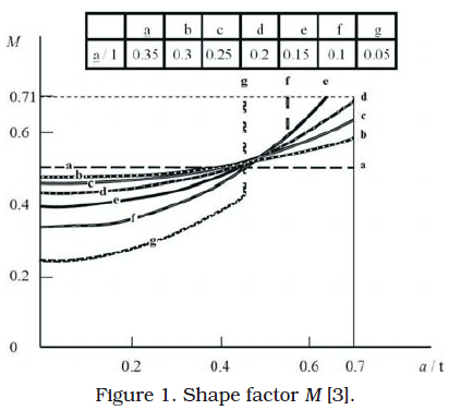
<body><![CDATA[<P ALIGN="justify"><FONT COLOR="#1f1a17" SIZE="2" FACE="Verdana"> <B>Failure analysis proposed by Ruiz&nbsp; and Corran [3]</B></FONT></P>     <P ALIGN="justify"><FONT COLOR="#1f1a17" SIZE="2" FACE="Verdana"> The shape factor <I>M </I>(obtained in <a href="#fig1">Figure 1</a>) <I>M </I>is function of the crack depth  and length. If crack depth is greater than 0.7 of the cylinder thickness,  the crack may behave in one of the following two manners. In first instance,  the crack has infinite length and depth <I>a</I>. It is supposed that crack propagates  through the cylinder thickness. The SIF is calculated by:</FONT></P>     <P ALIGN="justify"><FONT COLOR="#1f1a17" SIZE="2" FACE="Verdana"> <img border="0" src="/img/fbpe/rtfiuz/v32n3/art02ec2a.gif" width="225" height="38"></FONT></P>     
<P ALIGN="center"><a name="fig1"> <img border="0" src="/img/fbpe/rtfiuz/v32n3/art02fig1.gif" width="412" height="376"></a></P>     
<P ALIGN="justify"><FONT COLOR="#1f1a17" SIZE="2" FACE="Verdana"> In second instance, the crack length increases and the SIF is:</FONT></P>     <P ALIGN="justify"><FONT COLOR="#1f1a17" SIZE="2" FACE="Verdana"> <img border="0" src="/img/fbpe/rtfiuz/v32n3/art02ec2b.gif" width="208" height="29"></FONT></P>     
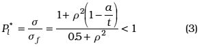
<P ALIGN="justify"><FONT COLOR="#1f1a17" SIZE="2" FACE="Verdana"> Summarizing, the SIF depends on the cracked geometry, the applied stress  and crack dimensions. For this reason equations (1), (2), (2a) and (2b)  are similar. In the case of the ductile failure, a limit analysis is done  considering an adimensional parameter <I>P</I></FONT><FONT COLOR="#1f1a17" SIZE="2" FACE="Bookman"><FONT COLOR="#1f1a17" FACE="Verdana"><SUB><I>l</I></SUB><SUP><I>*</I></SUP></FONT><FONT COLOR="#1f1a17" FACE="Verdana" SIZE="2">, which relates the required pressure  for the generation of general yield of a cracked pipe with the required  pressure for general yield of the same pipe without crack. For a longitudinal  crack (equation 3), where </FONT> </FONT><FONT COLOR="#1f1a17" SIZE="2" FACE="Symbol"> s</FONT><FONT COLOR="#1f1a17" SIZE="2" FACE="Bookman"><FONT COLOR="#1f1a17" FACE="Verdana"><SUB><I>f</I></SUB></FONT><FONT COLOR="#1f1a17" FACE="Verdana" SIZE="2"> &nbsp;is flow stress:</FONT></FONT></P>     <P ALIGN="justify"><FONT COLOR="#1f1a17" SIZE="2" FACE="Verdana"> <img border="0" src="/img/fbpe/rtfiuz/v32n3/art02ec3.gif" width="291" height="69"></FONT></P>     
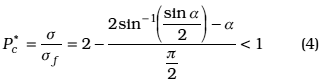
<P ALIGN="justify"><FONT COLOR="#1f1a17" SIZE="2" FACE="Verdana"> In the case of a <B>through wall thickness circumferential crack</B>, <I>P<sub>c</sub></I><SUP><I>*</I></SUP>, instead  of <I>P</I></FONT><FONT COLOR="#1f1a17" FACE="Verdana" SIZE="2"><SUB><I>l</I></SUB><SUP><I>*</I></SUP>.</FONT></P>     <P ALIGN="justify"><FONT COLOR="#1f1a17" SIZE="2" FACE="Verdana"> <B>Two cases are considered</B>. The first one is when the cracked cylinder is  under <B>internal pressure</B>, and the following equation is used:</FONT></P>     ]]></body>
<body><![CDATA[<P ALIGN="justify"><FONT COLOR="#1f1a17" SIZE="2" FACE="Verdana"> <img border="0" src="/img/fbpe/rtfiuz/v32n3/art02ec4.gif" width="321" height="81"></FONT></P>     
<P ALIGN="justify"><FONT COLOR="#1f1a17" SIZE="2" FACE="Verdana"> where:  </FONT><FONT COLOR="#1f1a17" SIZE="2" FACE="Symbol"> s</FONT><FONT COLOR="#1f1a17" SIZE="2" FACE="Verdana"><I> </I>is the longitudinal stress. In the second case, <I>M*</I> is the relation  between the ductile failure caused by a bending moment (</FONT><FONT COLOR="#1f1a17" SIZE="2" FACE="Bookman"><FONT COLOR="#1f1a17" FACE="Verdana" SIZE="2"><I><B>M</B></I></FONT><FONT COLOR="#1f1a17" SIZE="2" FACE="Bookman"><FONT COLOR="#1f1a17" FACE="Verdana"><SUB><I><B>b</B></I></SUB></FONT><FONT COLOR="#1f1a17" FACE="Verdana" SIZE="2">) of a cracked  pipe and the plastic failure bending moment (4</FONT></FONT></FONT><FONT COLOR="#1f1a17" SIZE="2" FACE="Symbol">s</FONT><FONT COLOR="#1f1a17" SIZE="2" FACE="Bookman"><FONT COLOR="#1f1a17" FACE="Verdana"><SUB><I>f </I></SUB></FONT> <FONT COLOR="#1f1a17" FACE="Verdana" SIZE="2"><I>t r</I></FONT><FONT COLOR="#1f1a17" FACE="Verdana"><SUP>2</SUP></FONT><FONT COLOR="#1f1a17" FACE="Verdana" SIZE="2">) of an uncracked  pipe <img border="0" src="/img/fbpe/rtfiuz/v32n3/art02ec4a.gif" width="81" height="35">. When this bending moment is parallel to the crack, the required  relation is:</FONT></FONT></P>     
<P ALIGN="justify"><FONT COLOR="#1f1a17" SIZE="2" FACE="Verdana"> <img border="0" src="/img/fbpe/rtfiuz/v32n3/art02ec5.gif" width="246" height="43"></FONT></P>     
<P ALIGN="justify"><FONT COLOR="#1f1a17" SIZE="2" FACE="Verdana"> Otherwise, when the bending moment is normal to the crack, the following  calculation has to be done:</FONT></P>     <P ALIGN="justify"><FONT COLOR="#1f1a17" SIZE="2" FACE="Verdana"> <img border="0" src="/img/fbpe/rtfiuz/v32n3/art02ec5a.gif" width="227" height="41"></FONT></P>     
<P ALIGN="justify"><FONT COLOR="#1f1a17" SIZE="2" FACE="Verdana"> In other words, <I>M</I></FONT><FONT COLOR="#1f1a17" SIZE="2" FACE="Bookman"><FONT COLOR="#1f1a17" FACE="Verdana"><SUP><I>*</I></SUP></FONT><FONT COLOR="#1f1a17" FACE="Verdana" SIZE="2"> is a geometrical factor and it depends on the way the  bending moment is applied. In the next step of this methodology, a safety  factor is obtained for brittle and ductile failure. For a brittle failure  in axial cracks:</FONT></FONT></P>     <P ALIGN="justify"><FONT COLOR="#1f1a17" SIZE="2" FACE="Verdana"> <img border="0" src="/img/fbpe/rtfiuz/v32n3/art02ec6.gif" width="196" height="46"></FONT></P>     
<P ALIGN="justify"><FONT COLOR="#1f1a17" SIZE="2" FACE="Verdana"> where <I>K</I></FONT><FONT COLOR="#1f1a17" SIZE="2" FACE="Bookman"><FONT COLOR="#1f1a17" FACE="Verdana"><SUB><I>IC</I></SUB></FONT><FONT COLOR="#1f1a17" FACE="Verdana" SIZE="2"> is a critical Stress Intensity Factor of the material. For a  <B>longitudinal crack</B>, a brittle failure occurs when the SF is equal or less  than one. In the case of ductile failure of longitudinal cracks, a similar  safety factor is evaluated:</FONT></FONT></P> </MULTICOL> <MULTICOL GUTTER="39" COLS="2">     <P ALIGN="justify"><FONT COLOR="#1f1a17" SIZE="2" FACE="Verdana"> <img border="0" src="/img/fbpe/rtfiuz/v32n3/art02ec7.gif" width="234" height="48"></FONT></P>     
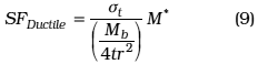
<P ALIGN="justify"><FONT COLOR="#1f1a17" SIZE="2" FACE="Verdana"> If the <I>SF</I></FONT><FONT COLOR="#1f1a17" SIZE="2" FACE="Bookman"><FONT COLOR="#1f1a17" FACE="Verdana"><SUB><I>Ductile</I></SUB></FONT><FONT COLOR="#1f1a17" FACE="Verdana" SIZE="2"> is equal or lower than one, failure occurs. In this case, </FONT> </FONT><FONT COLOR="#1f1a17" SIZE="2" FACE="Symbol"> s</FONT><FONT COLOR="#1f1a17" SIZE="2" FACE="Bookman"><FONT COLOR="#1f1a17" FACE="Verdana"><SUB><I>f</I></SUB></FONT><FONT COLOR="#1f1a17" FACE="Verdana" SIZE="2"> is the flow stress, </FONT> </FONT><FONT COLOR="#1f1a17" SIZE="2" FACE="Symbol"> s</FONT><FONT COLOR="#1f1a17" SIZE="2" FACE="Verdana"> is the design stress and <I>P</I></FONT><FONT COLOR="#1f1a17" FACE="Verdana" SIZE="2"><SUB><I>l</I></SUB><SUP><I>*</I></SUP> is a relation between  the fluency pressure of the uncracked pipe and the fluency pressure of  the cracked pipe. In order to know the behaviour of the cracked component,  the safety factors are compared. In the case of <B>circumferential cracks</B>,  the safety factor is calculated with the following relation. In this case  a longitudinal stress is generated and it may be considered as the resultant  of an axial load. When ductile failure occurs, the following evaluation  is carried on.</FONT></P>     ]]></body>
<body><![CDATA[<P ALIGN="justify"><FONT COLOR="#1f1a17" SIZE="2" FACE="Verdana"> <img border="0" src="/img/fbpe/rtfiuz/v32n3/art02ec8.gif" width="213" height="42"></FONT></P>     
<P ALIGN="justify"><FONT COLOR="#1f1a17" SIZE="2" FACE="Verdana"> and when there is a <B>bending moment</B> and ductile failure takes place:</FONT></P>     <P ALIGN="justify"><FONT COLOR="#1f1a17" SIZE="2" FACE="Verdana"> <img border="0" src="/img/fbpe/rtfiuz/v32n3/art02ec9.gif" width="232" height="58"></FONT></P>     
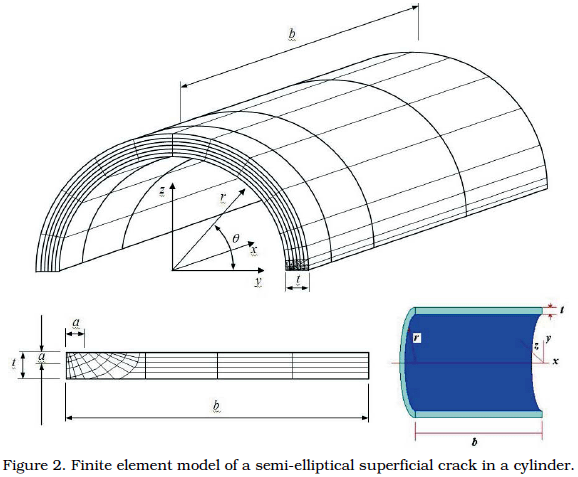
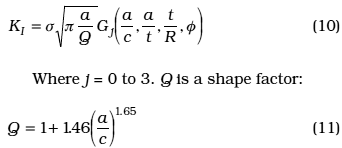
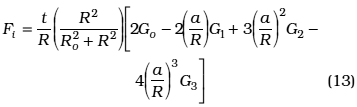
<P ALIGN="justify"><FONT COLOR="#1f1a17" SIZE="2" FACE="Verdana"> Summarizing, equation 7, 8 and 9 evaluate the safety factor related with  ductile failure. Their difference depends on crack geometry and loading  conditions.</FONT></P>     <P ALIGN="justify"><FONT COLOR="#1f1a17" SIZE="2" FACE="Verdana"> <B>ASME code analysis [4]</B></FONT></P>     <P ALIGN="justify"><FONT COLOR="#1f1a17" SIZE="2" FACE="Verdana"> Section XI of the ASME Boiler and Pressure Vessel Code establishes the  criteria and the requirements for service and pre-service inspection and  testing. For class 1 components, the article IWB 3000 of Division I establishes  the acceptance standards for cracked vessels, piping, bolting, pumps, etc.  If the crack size is greater than those allowed by the table IWB-3410-1,  then an analytical evaluation can be followed. In the case of Ferritic  steel pipe, the Code Case N463 [8] can be observed when the acceptance  standards are exceeded. Alternatively, crack evaluations in Austenitic  pipe can be done with the Code Case N-436 [9]. In general terms, the Code  Case N-463 has two acceptance criteria. The first one is function of crack  size, while the second depends on the applied stresses. Moreover, the failure  cases are considered in the evaluation phase, namely (1) limit load failure,  (2) elastoplastic fracture mechanics, where ductile crack propagation may  occur before reaching the limit load and (3) brittle failure, which is  analyzed with elastic Fracture Mechanics. Regarding case N-436, only limit  analysis is considered, because austenitic steels have high fracture toughness.</FONT></P>     <P ALIGN="justify"><FONT COLOR="#1f1a17" SIZE="2" FACE="Verdana"> <B>Numerical solutions proposed&nbsp; by RAJU-NEWMAN [5]</B></FONT></P>     <P ALIGN="justify"><FONT COLOR="#1f1a17" SIZE="2" FACE="Verdana"> Raju and Newman have evaluated numerically the SIF for a wide range of  elliptical cracks loaded under Mode I. FEM was used for longitudinally  cracked cylinder under internal pressure, when the defect is on the internal  or external surface (<a href="#fig2">Figure 2</a>). Furthermore, four stress distributions  through the thickness are considered, namely (1) Uniform, (2) Lineal, (3)  Quadratic, and (4) Cubic. From all these cases, the influence coefficients,  <I>G</I></FONT><FONT COLOR="#1f1a17" SIZE="2" FACE="Bookman"><FONT COLOR="#1f1a17" FACE="Verdana"><SUB><I>j</I></SUB></FONT><FONT COLOR="#1f1a17" FACE="Verdana" SIZE="2">, are obtained for other stress distributions like internal pressure  or thermal shock. According to <a href="#fig2">Figure 2</a>, the SIF of an external surface  crack, <I>K</I></FONT><FONT COLOR="#1f1a17" FACE="Verdana"><SUB><I>I</I></SUB></FONT><FONT COLOR="#1f1a17" FACE="Verdana" SIZE="2"> along its front is calculated with the following equation:</FONT></FONT></P>     <P ALIGN="center"><a name="fig2"> <img border="0" src="/img/fbpe/rtfiuz/v32n3/art02fig2.gif" width="578" height="477"></a></P>     
<P ALIGN="justify"><FONT COLOR="#1f1a17" SIZE="2" FACE="Verdana"> <img border="0" src="/img/fbpe/rtfiuz/v32n3/art02ec10.gif" width="342" height="148"></FONT></P>     
]]></body>
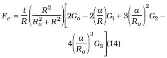
<body><![CDATA[<P ALIGN="justify"><FONT COLOR="#1f1a17" SIZE="2" FACE="Verdana"> Internal surface cracks in cylinders under internal pressure are evaluated  with the following relation:</FONT></P>     <P ALIGN="justify"><FONT COLOR="#1f1a17" SIZE="2" FACE="Verdana"> <img border="0" src="/img/fbpe/rtfiuz/v32n3/art02ec12.gif" width="298" height="52"></FONT></P>     
<P ALIGN="justify"><FONT COLOR="#1f1a17" SIZE="2" FACE="Verdana"> where F</FONT><FONT COLOR="#1f1a17" SIZE="2" FACE="Bookman"><FONT COLOR="#1f1a17" FACE="Verdana"><SUB>i</SUB></FONT><FONT COLOR="#1f1a17" FACE="Verdana" SIZE="2"> is a correction factor, which in terms of <I>G</I></FONT><FONT COLOR="#1f1a17" FACE="Verdana"><SUB><I>j</I></SUB></FONT><FONT COLOR="#1f1a17" FACE="Verdana" SIZE="2"> and Lam&#233; equation  is:</FONT></FONT></P>     <P ALIGN="justify"><FONT COLOR="#1f1a17" SIZE="2" FACE="Verdana"> <img border="0" src="/img/fbpe/rtfiuz/v32n3/art02ec13.gif" width="357" height="107"></FONT></P> </MULTICOL> <MULTICOL GUTTER="39" COLS="2">     
<P ALIGN="justify"><FONT COLOR="#1f1a17" SIZE="2" FACE="Verdana"> In the case of external longitudinal cracks, the factor <I>F</I></FONT><FONT COLOR="#1f1a17" SIZE="2" FACE="Bookman"><FONT COLOR="#1f1a17" FACE="Verdana"><SUB><I>i</I></SUB></FONT><FONT COLOR="#1f1a17" FACE="Verdana" SIZE="2"> is changed by  <I>F</I></FONT><FONT COLOR="#1f1a17" FACE="Verdana"><SUB><I>e</I></SUB></FONT><FONT COLOR="#1f1a17" FACE="Verdana" SIZE="2">,</FONT></FONT></P>     <P ALIGN="justify"><FONT COLOR="#1f1a17" SIZE="2" FACE="Verdana"> <img border="0" src="/img/fbpe/rtfiuz/v32n3/art02ec14.gif" width="335" height="117"></FONT></P>     
<P ALIGN="justify"><FONT COLOR="#1f1a17" SIZE="2" FACE="Verdana"> The values are obtained from [5] and they are integrated in EVTUBAG. Summarizing,  equations 10 and 12 evaluate the SIF. They depend on crack localization  (internal or external surface).</FONT></P>     <P ALIGN="center"><a name="fig3"> <img border="0" src="/img/fbpe/rtfiuz/v32n3/art02fig3.gif" width="487" height="434"></a></P>     
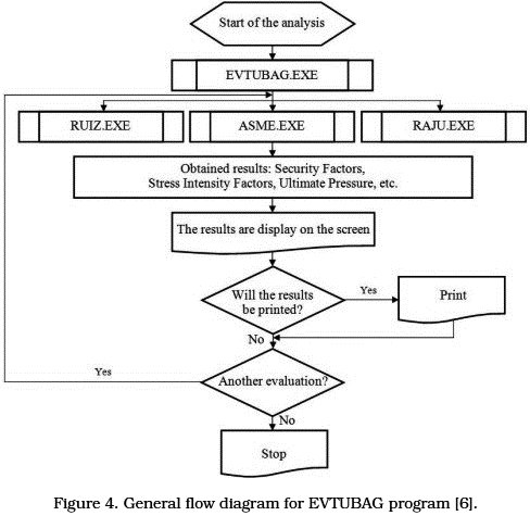
<P ALIGN="justify"><FONT COLOR="#1f1a17" SIZE="2" FACE="Verdana"> <B>Program Description</B></FONT></P>     <P ALIGN="justify"><FONT COLOR="#1f1a17" SIZE="2" FACE="Verdana"> EVTUBAG was written in Quick Basic 4.5 and runs in Pentium PC with a 16  MB Ram memory and 540 MB hard disk minimum. This program has four subroutines,  <a href="#fig4">Figure 4</a> shows its flow diagram.</FONT></P>     ]]></body>
<body><![CDATA[<P ALIGN="center"><a name="fig4"> <img border="0" src="/img/fbpe/rtfiuz/v32n3/art02fig4.gif" width="488" height="475"></a></P>     
<P ALIGN="justify"><FONT COLOR="#1f1a17" SIZE="2" FACE="Verdana"> The main one is EVTUBAG, which handles the input data that can be used  in the other three subroutines (RUIZ, ASME, RAJU). The subroutine RUIZ  follows the procedure described in [3]. The cases which can be analyzed  are <B>part through-wall</B> and <B>through wall thickness</B> <B>longitudinal cracks</B> under  the scope of brittle and ductile failure. Moreover, the ductile failure  of circumferential cracks is covered. For this purpose, axysimetric part  through-wall cracks under <B>internal pressure</B> and through wall thickness  cracks under internal pressure and/or bending moment may be calculated.  The ASME subroutine follows the crack size acceptance procedure proposed  in IWB-3514 section XI for nuclear power plant components for two situations:  (1) longitudinal cracks under internal pressure and (2) circumferential  cracks under internal pressure, bending moment and/or axial loading. It  has to keep in mind that the scope of ASME Code only considers the case  of part through-wall cracks.</FONT></P> </MULTICOL> <MULTICOL GUTTER="39" COLS="2">     <P ALIGN="justify"><FONT COLOR="#1f1a17" SIZE="2" FACE="Verdana"> When crack size is bigger than the acceptable standards, ASME subroutine  has two calculation procedures. The first one is for austenitic piping  (Code Case N-436) [9]. Alternatively, when the analyzed pipe is made by  ferritic steel, the Code Case N463 [8] is followed. In the RAJU subroutine,  the stress intensity factors are evaluated. Accordingly, part through-wall  and through wall thickness longitudinal cracked pipe under internal pressure  may be analyzed. Besides, there are two alternatives for the analysis of  circumferential cracks. The first one is related with axysimmetric and  semi elliptical part through-wall cracks under internal pressure. On the  other hand, the second case is related with the through wall thickness  cracks under internal pressure, bending moments and/or tensile loading.  Each of the subroutine mentioned above may be used independently or linked.  This program is complemented with a database, containing tabulated and  graphical data of ASME Code or the influence coefficients of Raju-Newman  solutions. A detailed description of the complete program can be found  in [6].</FONT></P>     <P ALIGN="justify"><FONT COLOR="#1f1a17" SIZE="2" FACE="Verdana"> <B>Validation of the Program</B></FONT></P>     <P ALIGN="justify"><FONT COLOR="#1f1a17" SIZE="2" FACE="Verdana"> The Mexican Regulatory Body required a program, which evaluates in a short  period of time and accurately the structural integrity of cracked cylindrical  geometries. Brittle and ductile failure mechanisms have to be considered  in such evaluations. In this case, the proposed procedures by ASME, Ruiz  and Raju Newman were included. The above mentioned methodologies are widely  accepted and they have been validated elsewhere in the past. For the case  of this paper, EVTUBAG is validated with the following cases:</FONT></P> </MULTICOL> <MULTICOL GUTTER="39" COLS="2">     <P ALIGN="justify"><FONT COLOR="#1f1a17" SIZE="2" FACE="Verdana"> <B>Longitudinal crack</B></FONT></P>     <P ALIGN="justify"><FONT COLOR="#1f1a17" SIZE="2" FACE="Verdana"> <B>CASE I (Longitudinal part through-wall wall crack)</B></FONT></P>     <P ALIGN="justify"><FONT COLOR="#1f1a17" SIZE="2" FACE="Verdana"> The internal radius and wall thickness of the cylinder analyzed is 2.286  m and 0.2286 m respectively. Crack length is 0.3429 m and its depth is  0.05715 m. Material properties are; Young Modulus is 206.85 GPa, Yield  Stress is 413.7 MPa and Poison&#180;s Ratio is 0.3. Two loading cases were considered.  In the first case, the internal pressure was 15.6 MPa and in the second  case, the internal pressure was 31.16 MPa. The results are shown in  <a href="#Table_2">Table  2</a>. In this case, brittle fracture was analyzed. For the purpose of validation,  it was considered the analysis reported in [10], in which the J-integral  value was obtained. In order to make a comparison, the J-values were transformed  to the SIF in plane strain conditions. As it can be seen, all the results  match.</FONT></P> </MULTICOL>     <P ALIGN="CENTER"><FONT COLOR="#1f1a17" SIZE="2" FACE="Verdana"> <a name="Table_2">Table 2</a></FONT></P>     <P ALIGN="CENTER"><FONT COLOR="#1f1a17" SIZE="2" FACE="Verdana"> Comparison of SIF values (Case I)&nbsp; </FONT></P>     ]]></body>
<body><![CDATA[<div align="center"> <TABLE cellspacing="1" width="580" border="1" id="table2"> <TR> <TD VALIGN="TOP" ROWSPAN="3">     <P ALIGN="CENTER" style="margin-top: 0; margin-bottom: 0"> <FONT COLOR="#1f1a17" SIZE="2" FACE="Verdana"> Internal Pressure</FONT></P>     <P ALIGN="CENTER" style="margin-top: 0; margin-bottom: 0"> <FONT COLOR="#1f1a17" SIZE="2" FACE="Verdana"> MPa</FONT></P> </TD> <TD VALIGN="TOP" COLSPAN="3">     <P ALIGN="CENTER"><FONT COLOR="#1f1a17" SIZE="2" FACE="Verdana"> Values from Reference [9]</FONT></P> </TD> <TD VALIGN="TOP" COLSPAN="6">     <P ALIGN="CENTER"><FONT COLOR="#1f1a17" SIZE="2" FACE="Verdana"> Results obtained with EVTUBAG for <I>K</I><SUB><I>I</I></SUB><I> </I>(MPa m<SUP>1/2</SUP>)</FONT></P> </TD> </TR> <TR> <TD WIDTH="37" VALIGN="TOP" ROWSPAN="2">     <P ALIGN="CENTER" style="margin-top: 0; margin-bottom: 0"> <FONT COLOR="#1f1a17" SIZE="2" FACE="Verdana"> J</FONT></P>     <P ALIGN="CENTER" style="margin-top: 0; margin-bottom: 0"> <FONT COLOR="#1f1a17" SIZE="2" FACE="Verdana"> (m)</FONT></P> </TD> <TD WIDTH="78" VALIGN="TOP" ROWSPAN="2">     <P ALIGN="CENTER" style="margin-top: 0; margin-bottom: 0"> <FONT COLOR="#1f1a17" SIZE="2" FACE="Verdana"> <I>K</I></FONT><SUB><I><FONT COLOR="#1f1a17" SIZE="2" FACE="Verdana">I</FONT></I></SUB></P>     <P ALIGN="CENTER" style="margin-top: 0; margin-bottom: 0"> <FONT COLOR="#1f1a17" SIZE="2" FACE="Verdana"> (MPa m<SUP>1/2</SUP>)</FONT></P> </TD> <TD WIDTH="46" VALIGN="TOP" ROWSPAN="2">     <P ALIGN="CENTER"><FONT COLOR="#1f1a17" SIZE="2" FACE="Verdana"> <I>K</I><SUB><I>I</I></SUB><I> / K</I><SUB>0</SUB></FONT></P> </TD> <TD WIDTH="104" VALIGN="TOP" COLSPAN="2">     ]]></body>
<body><![CDATA[<P ALIGN="CENTER"><FONT COLOR="#1f1a17" SIZE="2" FACE="Verdana"> Ruiz</FONT></P> </TD> <TD WIDTH="111" VALIGN="TOP" COLSPAN="2">     <P ALIGN="CENTER"><FONT COLOR="#1f1a17" SIZE="2" FACE="Verdana"> Raju</FONT></P> </TD> <TD WIDTH="109" VALIGN="TOP" COLSPAN="2">     <P ALIGN="CENTER"><FONT COLOR="#1f1a17" SIZE="2" FACE="Verdana"> ASME</FONT></P> </TD> </TR> <TR> <TD WIDTH="37" VALIGN="TOP">     <P ALIGN="CENTER"><FONT COLOR="#1f1a17" SIZE="2" FACE="Verdana"> <I>K</I><SUB><I>I</I></SUB></FONT></P> </TD> <TD WIDTH="63" VALIGN="TOP">     <P ALIGN="CENTER"><FONT COLOR="#1f1a17" SIZE="2" FACE="Verdana"> <I>K</I><SUB><I>I</I></SUB><I> / K</I><SUB>0</SUB></FONT></P> </TD> <TD WIDTH="49" VALIGN="TOP">     <P ALIGN="CENTER"><FONT COLOR="#1f1a17" SIZE="2" FACE="Verdana"> <I>K</I><SUB><I>I</I></SUB></FONT></P> </TD> <TD WIDTH="58" VALIGN="TOP">     <P ALIGN="CENTER"><FONT COLOR="#1f1a17" SIZE="2" FACE="Verdana"> <I>K</I><SUB><I>I</I></SUB><I> / K</I><SUB>0</SUB></FONT></P> </TD> <TD WIDTH="47" VALIGN="TOP">     <P ALIGN="CENTER"><FONT COLOR="#1f1a17" SIZE="2" FACE="Verdana"> <I>K</I><SUB><I>I</I></SUB></FONT></P> </TD> <TD WIDTH="59" VALIGN="TOP">     <P ALIGN="CENTER"><FONT COLOR="#1f1a17" SIZE="2" FACE="Verdana"> <I>K</I><SUB><I>I</I></SUB><I> / K</I><SUB>0</SUB></FONT></P> </TD> </TR> <TR> <TD WIDTH="59" VALIGN="TOP">     <P ALIGN="CENTER"><FONT COLOR="#1f1a17" SIZE="2" FACE="Verdana"> 15.6 </FONT></P> </TD> <TD WIDTH="37" VALIGN="TOP">     ]]></body>
<body><![CDATA[<P ALIGN="CENTER"><FONT COLOR="#1f1a17" SIZE="2" FACE="Verdana"> &nbsp;3.79</FONT></P> </TD> <TD WIDTH="78" VALIGN="TOP">     <P ALIGN="CENTER"><FONT COLOR="#1f1a17" SIZE="2" FACE="Verdana"> &nbsp;77.03</FONT></P> </TD> <TD WIDTH="46" VALIGN="TOP">     <P ALIGN="CENTER"><FONT COLOR="#1f1a17" SIZE="2" FACE="Verdana"> 1.11</FONT></P> </TD> <TD WIDTH="37" VALIGN="TOP">     <P ALIGN="CENTER"><FONT COLOR="#1f1a17" SIZE="2" FACE="Verdana"> &nbsp;74.7</FONT></P> </TD> <TD WIDTH="63" VALIGN="TOP">     <P ALIGN="CENTER"><FONT COLOR="#1f1a17" SIZE="2" FACE="Verdana"> 1.07</FONT></P> </TD> <TD WIDTH="49" VALIGN="TOP">     <P ALIGN="CENTER"><FONT COLOR="#1f1a17" SIZE="2" FACE="Verdana"> &nbsp;75.82</FONT></P> </TD> <TD WIDTH="58" VALIGN="TOP">     <P ALIGN="CENTER"><FONT COLOR="#1f1a17" SIZE="2" FACE="Verdana"> 1.09</FONT></P> </TD> <TD WIDTH="47" VALIGN="TOP">     <P ALIGN="CENTER"><FONT COLOR="#1f1a17" SIZE="2" FACE="Verdana"> &nbsp;79.77</FONT></P> </TD> <TD WIDTH="59" VALIGN="TOP">     <P ALIGN="CENTER"><FONT COLOR="#1f1a17" SIZE="2" FACE="Verdana"> 1.15</FONT></P> </TD> </TR> <TR> <TD WIDTH="59" VALIGN="TOP">     <P ALIGN="CENTER"><FONT COLOR="#1f1a17" SIZE="2" FACE="Verdana"> 31.16</FONT></P> </TD> <TD WIDTH="37" VALIGN="TOP">     ]]></body>
<body><![CDATA[<P ALIGN="CENTER"><FONT COLOR="#1f1a17" SIZE="2" FACE="Verdana"> 17.91</FONT></P> </TD> <TD WIDTH="78" VALIGN="TOP">     <P ALIGN="CENTER"><FONT COLOR="#1f1a17" SIZE="2" FACE="Verdana"> 167.47</FONT></P> </TD> <TD WIDTH="46" VALIGN="TOP">     <P ALIGN="CENTER"><FONT COLOR="#1f1a17" SIZE="2" FACE="Verdana"> 1.2</FONT></P> </TD> <TD WIDTH="37" VALIGN="TOP">     <P ALIGN="CENTER"><FONT COLOR="#1f1a17" SIZE="2" FACE="Verdana"> 149.4</FONT></P> </TD> <TD WIDTH="63" VALIGN="TOP">     <P ALIGN="CENTER"><FONT COLOR="#1f1a17" SIZE="2" FACE="Verdana"> 1.07</FONT></P> </TD> <TD WIDTH="49" VALIGN="TOP">     <P ALIGN="CENTER"><FONT COLOR="#1f1a17" SIZE="2" FACE="Verdana"> 151.6</FONT></P> </TD> <TD WIDTH="58" VALIGN="TOP">     <P ALIGN="CENTER"><FONT COLOR="#1f1a17" SIZE="2" FACE="Verdana"> 1.09</FONT></P> </TD> <TD WIDTH="47" VALIGN="TOP">     <P ALIGN="CENTER"><FONT COLOR="#1f1a17" SIZE="2" FACE="Verdana"> 159.5</FONT></P> </TD> <TD WIDTH="59" VALIGN="TOP">     <P ALIGN="CENTER"><FONT COLOR="#1f1a17" SIZE="2" FACE="Verdana"> 1.15</FONT></P> </TD> </TR> </TABLE> </div> <MULTICOL GUTTER="39" COLS="2">     <P ALIGN="justify"><FONT COLOR="#1f1a17" SIZE="2" FACE="Verdana"> <B>CASE II (Longitudinal through wall thickness crack)</B><I><B>&nbsp;</B></I> </FONT></P>     ]]></body>
<body><![CDATA[<P ALIGN="justify"><FONT COLOR="#1f1a17" SIZE="2" FACE="Verdana"> One brittle failure case was proposed, which was previously solved by the  authors with the Finite Element Method using ANSYS 9.0 code. The external  diameter and wall thickness are 0.508 m and 0.015 m respectively. Crack  length is 0.492 m. Regarding the material properties, Young&#180;s Modulus is  210 GPa and Poisson Ratio is 0.3. As fracture conditions are analyzed,  the elastic properties are only required. All the calculations were performed  with an internal pressure of 36.7 MPa. In order to make a complete comparison,  <I>K</I></FONT><FONT COLOR="#1f1a17" SIZE="2" FACE="Bookman"><FONT COLOR="#1f1a17" FACE="Verdana"><SUB><I>I</I></SUB></FONT><FONT COLOR="#1f1a17" FACE="Verdana" SIZE="2"> was calculated with other equations which have the following general  form <img border="0" src="/img/fbpe/rtfiuz/v32n3/art02ec14a.gif" width="106" height="19">. The main difference is its geometrical factor, which  it takes in to account the crack length, <I>a</I>, the vessel radius <I>R</I>, and the  vessel wall thickness <I>t</I>. In all cases, the hoop stress was introduced.  Results are shown in <a href="#Table_3">Table 3</a>. In the evaluation of the results, it is important  to keep in mind that the Raju-Newman procedure is based on a FEM analysis.  Also, both solutions are in agreement with the one obtained with the geometrical  factor reported in [11]. On the other hand, the solution of Ruiz and Corran  and the one obtained with the correction factor reported in [12] are similar.  All these analyses are appropriate for brittle behaviour and the geometry  of the cracked body plays an important role. Therefore, all the solutions  may be as a range of solutions.</FONT></FONT></P> </MULTICOL>     
<P ALIGN="CENTER"><FONT COLOR="#1f1a17" SIZE="2" FACE="Verdana"> <a name="Table_3">Table 3</a></FONT></P>     <P ALIGN="CENTER"><FONT COLOR="#1f1a17" SIZE="2" FACE="Verdana"> Comparison of SIF values obtained by diverse methods (Case II).&nbsp; </FONT></P>     <div align="center"> <TABLE cellspacing="1" width="580" border="1" id="table3"> <TR> <TD WIDTH="216" VALIGN="TOP">     <P ALIGN="CENTER"><FONT COLOR="#1f1a17" SIZE="2" FACE="Verdana"> Equation</FONT></P> </TD> <TD WIDTH="128" VALIGN="TOP">     <P ALIGN="CENTER"><FONT COLOR="#1f1a17" SIZE="2" FACE="Verdana"> <I>K</I><SUB><I>I</I></SUB><I> </I>(GPa m</FONT><FONT COLOR="#1f1a17" SIZE="2" FACE="Bookman"><FONT COLOR="#1f1a17" FACE="Verdana"><SUP>1/2</SUP></FONT><FONT COLOR="#1f1a17" SIZE="2" FACE="Verdana">)</FONT></FONT></P> </TD> <TD WIDTH="128" VALIGN="TOP">     <P ALIGN="CENTER"><FONT COLOR="#1f1a17" SIZE="2" FACE="Verdana"> <I>K</I><SUB><I>I</I></SUB><I> / K</I></FONT><FONT COLOR="#1f1a17" FACE="Verdana" SIZE="2"><SUB>0</SUB></FONT></P> </TD> <TD WIDTH="128" VALIGN="TOP">     <P ALIGN="CENTER"><FONT COLOR="#1f1a17" SIZE="2" FACE="Verdana"> Reference</FONT></P> </TD> </TR> <TR> <TD WIDTH="216" VALIGN="TOP">     <P ALIGN="LEFT"><FONT COLOR="#1f1a17" SIZE="2" FACE="Verdana"> &nbsp;<img border="0" src="/img/fbpe/rtfiuz/v32n3/art02ect3a.gif" width="120" height="42"></FONT></P> </TD> <TD WIDTH="128">     
<P ALIGN="CENTER"><FONT COLOR="#1f1a17" SIZE="2" FACE="Verdana"> 2.78</FONT></P> </TD> <TD WIDTH="128">     ]]></body>
<body><![CDATA[<P ALIGN="CENTER"><FONT COLOR="#1f1a17" SIZE="2" FACE="Verdana"> 21.28</FONT></P> </TD> <TD WIDTH="128">     <P ALIGN="CENTER"><FONT COLOR="#1f1a17" SIZE="2" FACE="Verdana"> [10]</FONT></P> </TD> </TR> <TR> <TD WIDTH="216" VALIGN="TOP">     <P ALIGN="LEFT"><FONT COLOR="#1f1a17" SIZE="2" FACE="Verdana"> FEM</FONT></P> </TD> <TD WIDTH="128" VALIGN="TOP">     <P ALIGN="CENTER"><FONT COLOR="#1f1a17" SIZE="2" FACE="Verdana"> 2.26</FONT></P> </TD> <TD WIDTH="128" VALIGN="TOP">     <P ALIGN="CENTER"><FONT COLOR="#1f1a17" SIZE="2" FACE="Verdana"> 17.30</FONT></P> </TD> <TD WIDTH="128" VALIGN="TOP">     <P ALIGN="CENTER"><FONT COLOR="#1f1a17" SIZE="2" FACE="Verdana"> ANSYS 9.0</FONT></P> </TD> </TR> <TR> <TD WIDTH="216" VALIGN="TOP">     <P ALIGN="LEFT"><FONT COLOR="#1f1a17" SIZE="2" FACE="Verdana"> &nbsp;<img border="0" src="/img/fbpe/rtfiuz/v32n3/art02ect3b.gif" width="220" height="43"></FONT></P> </TD> <TD WIDTH="128">     
<P ALIGN="CENTER"><FONT COLOR="#1f1a17" SIZE="2" FACE="Verdana"> 2.25</FONT></P> </TD> <TD WIDTH="128">     <P ALIGN="CENTER"><FONT COLOR="#1f1a17" SIZE="2" FACE="Verdana"> 17.22</FONT></P> </TD> <TD WIDTH="128">     <P ALIGN="CENTER"><FONT COLOR="#1f1a17" SIZE="2" FACE="Verdana"> [11]</FONT></P> </TD> </TR> <TR> <TD WIDTH="216" VALIGN="TOP">     ]]></body>
<body><![CDATA[<P ALIGN="LEFT"><FONT COLOR="#1f1a17" SIZE="2" FACE="Verdana"> Ruiz</FONT></P> </TD> <TD WIDTH="128" VALIGN="TOP">     <P ALIGN="CENTER"><FONT COLOR="#1f1a17" SIZE="2" FACE="Verdana"> 2.75</FONT></P> </TD> <TD WIDTH="128" VALIGN="TOP">     <P ALIGN="CENTER"><FONT COLOR="#1f1a17" SIZE="2" FACE="Verdana"> 21.08</FONT></P> </TD> <TD WIDTH="128" VALIGN="TOP">     <P ALIGN="CENTER"><FONT COLOR="#1f1a17" SIZE="2" FACE="Verdana"> EVTUBAG</FONT></P> </TD> </TR> <TR> <TD WIDTH="216" VALIGN="TOP">     <P ALIGN="LEFT"><FONT COLOR="#1f1a17" SIZE="2" FACE="Verdana"> Raju-Newman</FONT></P> </TD> <TD WIDTH="128" VALIGN="TOP">     <P ALIGN="CENTER"><FONT COLOR="#1f1a17" SIZE="2" FACE="Verdana"> 2.32</FONT></P> </TD> <TD WIDTH="128" VALIGN="TOP">     <P ALIGN="CENTER"><FONT COLOR="#1f1a17" SIZE="2" FACE="Verdana"> 17.77</FONT></P> </TD> <TD WIDTH="128" VALIGN="TOP">     <P ALIGN="CENTER"><FONT COLOR="#1f1a17" SIZE="2" FACE="Verdana"> EVTUBAG</FONT></P> </TD> </TR> <TR> <TD WIDTH="216" VALIGN="TOP">     <P ALIGN="LEFT"><FONT COLOR="#1f1a17" SIZE="2" FACE="Verdana"> ASME</FONT></P> </TD> <TD WIDTH="128" VALIGN="TOP" BGCOLOR="#c3c3c2"> <font face="Verdana" size="2">&nbsp;</font></TD> <TD WIDTH="128" VALIGN="TOP" BGCOLOR="#c3c3c2"> <font face="Verdana" size="2">&nbsp;</font></TD> <TD WIDTH="128" VALIGN="TOP">     <P ALIGN="CENTER"><FONT COLOR="#1f1a17" SIZE="2" FACE="Verdana"> EVTUBAG</FONT></P> </TD> </TR> </TABLE> </div> <MULTICOL GUTTER="39" COLS="2">     ]]></body>
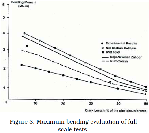
<body><![CDATA[<P ALIGN="justify"><FONT COLOR="#1f1a17" SIZE="2" FACE="Verdana"> <B>Circumferential crack</B></FONT></P>     <P ALIGN="justify"><FONT COLOR="#1f1a17" SIZE="2" FACE="Verdana"> <B>CASE III (Circumferential through wall thickness crack)</B></FONT></P>     <P ALIGN="justify"><FONT COLOR="#1f1a17" SIZE="2" FACE="Verdana"> The experimental results obtained in the US Nuclear Regulatory Commission  Degraded Piping Program Phase II [13], were considered. In this case, a  full scale test of a straight pipe, under bending loading at 288&#176;C, was  done. Its external diameter and thickness are 0.7112 m and 0.0236 m respectively.  The pipe material was steel A516 Gr 70. One of the objectives was the determination  of the maximum allowable bending moment. Therefore, two conditions were  analyzed. In the first case, a short circumferential crack was introduced;  its length was 6% of the circular perimeter. In a second instance, a long  circumferential crack was evaluated. Its length was 37% of the circular  perimeter of the pipe. The experimental evidence has shown that circumferential  short cracks tend to have a ductile behaviour, while circumferential long  cracks tend to have a brittle behaviour (<a href="#fig3">Figure 3</a>). Also, in this figure,  the results obtained with the Net Section Collapse (NSC) are plotted. This  can be considered as the upper limit of the range of solutions. On the  other, the lower limit of the range of solutions is obtained with the IWB  3650 procedure of ASME.&nbsp; </FONT></P> </MULTICOL> <MULTICOL GUTTER="39" COLS="2">     <P ALIGN="justify"><FONT COLOR="#1f1a17" SIZE="2" FACE="Verdana"> The last two evaluations were done within the full scale test programme  mentioned above. The Ruiz and Corran procedure was run for different crack  lengths. The results are close to those obtained experimentally. Also,  such results tend to be close to those obtained with the IWB 3650. Alternatively,  the modified Raju-Newmann results overestimate the failure moment. It is  important to keep in mind that the limit load solutions provided by Zahoor  [14] were introduced as a complement for the Raju-Newman procedures. These  results are close to the NSC solution. In general terms, both procedures  give results within the range of solutions described before. The results  obtained with the Ruiz and Raju-Newman-Zahoor procedures are shown in  <a href="#Table_4">Table  4</a>.</FONT></P> </MULTICOL>     <P ALIGN="CENTER"><FONT COLOR="#1f1a17" SIZE="2" FACE="Verdana"> <a name="Table_4">Table 4</a></FONT></P>     <P ALIGN="CENTER"><FONT COLOR="#1f1a17" SIZE="2" FACE="Verdana"> Maximum allowed bending moment (Case III)&nbsp; </FONT></P>     <div align="center"> <TABLE cellspacing="1" width="572" border="1" id="table4"> <TR> <TD VALIGN="TOP" COLSPAN="3">     <P ALIGN="CENTER"><FONT COLOR="#1f1a17" SIZE="1" FACE="Verdana"> Test conditions&nbsp; </FONT></P> </TD> <TD VALIGN="TOP" COLSPAN="4">     <P ALIGN="CENTER" style="margin-top: 0; margin-bottom: 0"> <font face="Verdana" size="1"><i>&nbsp;&nbsp;&nbsp;&nbsp;&nbsp;&nbsp;&nbsp;&nbsp;&nbsp;&nbsp;&nbsp;&nbsp;  Maximun moment applied intests</i></font></P>     <P ALIGN="center" style="margin-top: 0; margin-bottom: 0"> <font face="Verdana" size="1"><i>Ratio</i> = </font> <font size="1" face="Symbol">¾¾¾¾¾¾¾¾¾¾¾¾¾¾¾¾¾¾¾</font></P>     ]]></body>
<body><![CDATA[<P ALIGN="center" style="margin-top: 0; margin-bottom: 0"> <font face="Verdana" size="1">&nbsp;&nbsp;&nbsp;&nbsp;&nbsp;&nbsp;&nbsp; <i> Maximun moment calculated</i></font></P> </TD> </TR> <TR> <TD WIDTH="81" VALIGN="TOP">     <P ALIGN="CENTER"><FONT COLOR="#1f1a17" SIZE="1" FACE="Verdana"> Test</FONT></P> </TD> <TD WIDTH="126" VALIGN="TOP">     <P ALIGN="CENTER"><FONT COLOR="#1f1a17" SIZE="1" FACE="Verdana"> Crack length/pipe circular perimeter</FONT></P>     <P ALIGN="CENTER"><FONT COLOR="#1f1a17" SIZE="1" FACE="Verdana"> <I>l</I>/(</FONT><FONT COLOR="#1f1a17" SIZE="2" FACE="Symbol">p</FONT><FONT COLOR="#1f1a17" SIZE="1" FACE="Verdana"><I>D</I>)</FONT></P> </TD> <TD WIDTH="95" VALIGN="TOP">     <P ALIGN="CENTER"><FONT COLOR="#1f1a17" SIZE="1" FACE="Verdana"> Maximum experimental moment</FONT></P>     <P ALIGN="CENTER"><FONT COLOR="#1f1a17" SIZE="1" FACE="Verdana"> (</FONT><FONT COLOR="#1f1a17" SIZE="2" FACE="Symbol">k</FONT><I><FONT COLOR="#1f1a17" SIZE="1" FACE="Verdana">N-m</FONT></I><FONT COLOR="#1f1a17" SIZE="1" FACE="Verdana">)</FONT></P> </TD> <TD WIDTH="56" VALIGN="TOP">     <P ALIGN="CENTER"><FONT COLOR="#1f1a17" SIZE="1" FACE="Verdana"> NSC</FONT></P> </TD> <TD WIDTH="53" VALIGN="TOP">     <P ALIGN="CENTER"><FONT COLOR="#1f1a17" SIZE="1" FACE="Verdana"> IWB 3650</FONT></P> </TD> <TD WIDTH="43" VALIGN="TOP">     <P ALIGN="CENTER"><FONT COLOR="#1f1a17" SIZE="1" FACE="Verdana"> Ruiz</FONT></P> </TD> <TD WIDTH="80" VALIGN="TOP">     <P ALIGN="CENTER"><FONT COLOR="#1f1a17" SIZE="1" FACE="Verdana"> Raju Newman Zahoor</FONT></P> </TD> </TR> <TR> <TD WIDTH="81" VALIGN="TOP">     ]]></body>
<body><![CDATA[<P ALIGN="LEFT"><FONT COLOR="#1f1a17" SIZE="1" FACE="Verdana"> 1.1.1.21 [14]</FONT></P> </TD> <TD WIDTH="126" VALIGN="TOP">     <P ALIGN="CENTER"><FONT COLOR="#1f1a17" SIZE="1" FACE="Verdana"> 0.0625 (short crack)</FONT></P> </TD> <TD WIDTH="95" VALIGN="TOP">     <P ALIGN="CENTER"><FONT COLOR="#1f1a17" SIZE="1" FACE="Verdana"> 3246</FONT></P> </TD> <TD WIDTH="56" VALIGN="TOP">     <P ALIGN="CENTER"><FONT COLOR="#1f1a17" SIZE="1" FACE="Verdana"> 0.868</FONT></P> </TD> <TD WIDTH="53" VALIGN="TOP">     <P ALIGN="CENTER"><FONT COLOR="#1f1a17" SIZE="1" FACE="Verdana"> 1.535</FONT></P> </TD> <TD WIDTH="43" VALIGN="TOP">     <P ALIGN="CENTER"><FONT COLOR="#1f1a17" SIZE="1" FACE="Verdana"> 1.114</FONT></P> </TD> <TD WIDTH="80" VALIGN="TOP">     <P ALIGN="CENTER"><FONT COLOR="#1f1a17" SIZE="1" FACE="Verdana"> 0.875</FONT></P> </TD> </TR> <TR> <TD WIDTH="81" VALIGN="TOP">     <P ALIGN="LEFT"><FONT COLOR="#1f1a17" SIZE="1" FACE="Verdana"> 4111-2 [12]</FONT></P> </TD> <TD WIDTH="126" VALIGN="TOP">     <P ALIGN="CENTER"><FONT COLOR="#1f1a17" SIZE="1" FACE="Verdana"> 0.37 (long crack)</FONT></P> </TD> <TD WIDTH="95" VALIGN="TOP">     <P ALIGN="CENTER"><FONT COLOR="#1f1a17" SIZE="1" FACE="Verdana"> 1204</FONT></P> </TD> <TD WIDTH="56" VALIGN="TOP">     ]]></body>
<body><![CDATA[<P ALIGN="CENTER"><FONT COLOR="#1f1a17" SIZE="1" FACE="Verdana"> 0.738</FONT></P> </TD> <TD WIDTH="53" VALIGN="TOP">     <P ALIGN="CENTER"><FONT COLOR="#1f1a17" SIZE="1" FACE="Verdana"> 1.131</FONT></P> </TD> <TD WIDTH="43" VALIGN="TOP">     <P ALIGN="CENTER"><FONT COLOR="#1f1a17" SIZE="1" FACE="Verdana"> 0.984</FONT></P> </TD> <TD WIDTH="80" VALIGN="TOP">     <P ALIGN="CENTER"><FONT COLOR="#1f1a17" SIZE="1" FACE="Verdana"> 0.822</FONT></P> </TD> </TR> </TABLE> </div> <MULTICOL GUTTER="39" COLS="2">     <P ALIGN="justify"><FONT COLOR="#1f1a17" SIZE="2" FACE="Verdana"> They were compared against the experimental results and the evaluations  performed with Net Section Collapse (NSC) and IWB 3650 of ASME procedures  reported in [13, 15 and 16]<B>.</B> In this case an adimensional comparison is  made, the ratio between the maximum moment applied in the experimental  tests and the maximum moment calculated with the methods considered. In  fact, the solutions which are closed to the unity may be considered as  the best. For the case of the short crack (6% of the pipe perimeter), an  elastoplastic behaviour was observed. It is important to keep in mind that  it is appropriate for the analysis of brittle behaviour. In the case of  the <B>long crack</B>, it was also observed an elasto plastic failure. The results  obtained with the Ruiz-Corran behaviour were close to the experimental  result. The modified Raju-Newmann analysis also gave a result which is  close to the experimental failure moment. As it was expected, the NSC and  the IWB 3650 evaluate the failure moment, which are in the limits of the  range of solutions. In general terms, the evaluations of EVTUBAG are in  line with the experimental evaluation.<B>&nbsp;</B> </FONT></P>     <P ALIGN="justify"><FONT COLOR="#1f1a17" SIZE="2" FACE="Verdana"> <B>Conclusions&nbsp;</B> </FONT></P>     <P ALIGN="justify"><FONT COLOR="#1f1a17" SIZE="2" FACE="Verdana"> It was shown in this paper that the program EVTUBAG can perform complete  structural integrity assessments on cracked cylindrical components. In  this case, it is avoided the use of numerical analysis, such as the Finite  Element method, which demands a large amount of computing resources. Besides,  this sort of analyses requires a lot of time. All the cases that are presented  in this paper were calculated in a short period and they only required  a few amount of computing resources. Actually, this program is being used  by the Mexican nuclear regulatory body. Another advantage of EVTUBAG program  is that diverse methodologies are concentrated in one programme and they  can be run together. Furthermore, ductile and brittle failure can be evaluated.  In the first case, fracture mechanics concepts are taken into account,  while in the second case, the failure is evaluated since the point of view  of limit analysis. Therefore, the analyst has a scope of solutions which  can be compared among them. The analyst has to keep in mind that during  operation, the material properties could be degraded. In consequence, it  is important to use in the evaluations the actual properties of the material.  The results presented in this paper and other cases that were used to evaluate  the performance of the program showed a good convergence with the solutions.  Even if EVTUBAG uses simple equations, this fast method has acceptable  agreement with the known formal solutions.&nbsp; </FONT></P> </MULTICOL> <MULTICOL GUTTER="39" COLS="2">     <P ALIGN="justify"><FONT COLOR="#1f1a17" SIZE="2" FACE="Verdana"> <B>Acknowledgements&nbsp;</B> </FONT></P>     <P ALIGN="justify"><FONT COLOR="#1f1a17" SIZE="2" FACE="Verdana"> The authors gratefully acknowledge the financial support granted by de  Consejo Nacional de Ciencia y Tecnolog&#237;a and the Instituto Polit&#233;cnico  Nacional. Also, it is in high recognition the support given by Mr. Pablo  Ruiz L&#243;pez of the Comisi&#243;n Nacional de Seguridad Nuclear y Salvaguardas.&nbsp; </FONT></P>     <P ALIGN="justify"><FONT COLOR="#1f1a17" SIZE="2" FACE="Verdana"> <B>Notation&nbsp;</B> </FONT></P>     ]]></body>
<body><![CDATA[<P ALIGN="justify"><FONT COLOR="#1f1a17" SIZE="2" FACE="Verdana"> <I>a</I>&nbsp;:&nbsp; Half width&nbsp; </FONT></P>     <P ALIGN="justify"><FONT COLOR="#1f1a17" SIZE="2" FACE="Verdana"> <I>D</I></FONT><FONT COLOR="#1f1a17" SIZE="2" FACE="Bookman"><FONT COLOR="#1f1a17" FACE="Verdana"><SUB><I>e</I></SUB></FONT><FONT COLOR="#1f1a17" FACE="Verdana" SIZE="2"><I>&nbsp;</I>:<I>&nbsp;</I></FONT></FONT><FONT COLOR="#1f1a17" SIZE="2" FACE="Verdana"> External diameter&nbsp; </FONT></P>     <P ALIGN="justify"><FONT COLOR="#1f1a17" SIZE="2" FACE="Verdana"> <I>G</I></FONT><FONT COLOR="#1f1a17" SIZE="2" FACE="Bookman"><FONT COLOR="#1f1a17" FACE="Verdana"><SUB><I>j</I></SUB></FONT><FONT COLOR="#1f1a17" FACE="Verdana" SIZE="2"><I>&nbsp;</I>:<I>&nbsp;</I></FONT></FONT><FONT COLOR="#1f1a17" SIZE="2" FACE="Verdana"> Influence coefficients&nbsp; </FONT></P>     <P ALIGN="justify"><FONT COLOR="#1f1a17" SIZE="2" FACE="Verdana"> <I>K</I></FONT><FONT COLOR="#1f1a17" SIZE="2" FACE="Bookman"><FONT COLOR="#1f1a17" FACE="Verdana"><SUB><I>I</I></SUB></FONT><FONT COLOR="#1f1a17" FACE="Verdana" SIZE="2">&nbsp;:&nbsp;</FONT></FONT><FONT COLOR="#1f1a17" SIZE="2" FACE="Verdana"> Stress Intensity Factor (mode I)&nbsp; </FONT></P>     <P ALIGN="justify"><FONT COLOR="#1f1a17" SIZE="2" FACE="Verdana"> <I>K</I></FONT><FONT COLOR="#1f1a17" SIZE="2" FACE="Bookman"><FONT COLOR="#1f1a17" FACE="Verdana"><SUB><I>IC</I></SUB></FONT><FONT COLOR="#1f1a17" FACE="Verdana" SIZE="2">&nbsp;:&nbsp;</FONT></FONT><FONT COLOR="#1f1a17" SIZE="2" FACE="Verdana"> Critical Stress Intensity Factor (mode I)&nbsp; </FONT></P>     <P ALIGN="justify"><FONT COLOR="#1f1a17" SIZE="2" FACE="Verdana"> <I>l</I>&nbsp;:&nbsp; Crack length&nbsp; </FONT></P>     <P ALIGN="justify"><FONT COLOR="#1f1a17" SIZE="2" FACE="Verdana"> <I>M</I>&nbsp;:&nbsp; Shape factor&nbsp; </FONT></P>     <P ALIGN="justify"><FONT COLOR="#1f1a17" SIZE="2" FACE="Verdana"> <I>M</I>*:&nbsp; Adimensional moment parameter&nbsp; </FONT></P>     <P ALIGN="justify"><FONT COLOR="#1f1a17" SIZE="2" FACE="Verdana"> <I>M</I></FONT><FONT COLOR="#1f1a17" SIZE="2" FACE="Bookman"><FONT COLOR="#1f1a17" FACE="Verdana"><SUB><I>b </I></SUB></FONT> <FONT COLOR="#1f1a17" FACE="Verdana" SIZE="2">:</FONT><FONT COLOR="#1f1a17" FACE="Verdana"><SUB><I>&nbsp;</I></SUB></FONT></FONT><FONT COLOR="#1f1a17" SIZE="2" FACE="Verdana"> Bending moment&nbsp; </FONT></P>     <P ALIGN="justify"><FONT COLOR="#1f1a17" SIZE="2" FACE="Verdana"> <I>P</I></FONT><FONT COLOR="#1f1a17" SIZE="2" FACE="Bookman"><FONT COLOR="#1f1a17" FACE="Verdana"><SUB><I>c</I></SUB></FONT><FONT COLOR="#1f1a17" FACE="Verdana" SIZE="2"><I>*</I>:<I>&nbsp;</I></FONT></FONT><FONT COLOR="#1f1a17" SIZE="2" FACE="Verdana"> Adimensional pressure parameter, for pipes with circumferential cracks<I>&nbsp;</I> </FONT></P>     ]]></body>
<body><![CDATA[<P ALIGN="justify"><FONT COLOR="#1f1a17" SIZE="2" FACE="Verdana"> P</FONT><FONT COLOR="#1f1a17" SIZE="2" FACE="Bookman"><FONT COLOR="#1f1a17" FACE="Verdana"><SUB><I>l</I></SUB></FONT><FONT COLOR="#1f1a17" FACE="Verdana" SIZE="2"><I>*</I>:&nbsp;</FONT></FONT><FONT COLOR="#1f1a17" SIZE="2" FACE="Verdana"> Adimensional pressure parameter, for pipes with longitudinal cracks&nbsp; </FONT></P>     <P ALIGN="justify"><FONT COLOR="#1f1a17" SIZE="2" FACE="Verdana"> <I>Q</I>&nbsp;:&nbsp; Geometrical shape factor&nbsp; </FONT></P>     <P ALIGN="justify"><FONT COLOR="#1f1a17" SIZE="2" FACE="Verdana"> <I>t </I>:<I>&nbsp;</I> Cylinder wall thickness&nbsp; </FONT></P>     <P ALIGN="justify"><FONT COLOR="#1f1a17" FACE="Symbol" SIZE="2">s</FONT><FONT COLOR="#1f1a17" FACE="Verdana" SIZE="2">&nbsp;:&nbsp; Longitudinal stress&nbsp; </FONT></P>     <P ALIGN="justify"><FONT COLOR="#1f1a17" FACE="Symbol" SIZE="2">s</FONT><I><FONT COLOR="#1f1a17" SIZE="2" FACE="Bookman"> </FONT></I><FONT COLOR="#1f1a17" SIZE="2" FACE="Bookman"> <FONT COLOR="#1f1a17" FACE="Verdana"><SUB><I>f</I></SUB></FONT><FONT COLOR="#1f1a17" FACE="Verdana" SIZE="2">&nbsp;:&nbsp;</FONT></FONT><FONT COLOR="#1f1a17" SIZE="2" FACE="Verdana"> Flow stress&nbsp; </FONT></P>     <P ALIGN="justify"><FONT COLOR="#1f1a17" FACE="Symbol" SIZE="2">s</FONT><I><FONT COLOR="#1f1a17" SIZE="2" FACE="Bookman"> </FONT></I><FONT COLOR="#1f1a17" SIZE="2" FACE="Bookman"> <FONT COLOR="#1f1a17" FACE="Verdana"><SUB><I>H&nbsp;</I></SUB></FONT><FONT COLOR="#1f1a17" FACE="Verdana" SIZE="2">:</FONT><FONT COLOR="#1f1a17" FACE="Verdana"><SUB><I>&nbsp;</I></SUB></FONT></FONT><FONT COLOR="#1f1a17" SIZE="2" FACE="Verdana"> Hoop stress&nbsp; </FONT></P>     <P ALIGN="justify"><FONT COLOR="#1f1a17" SIZE="2" FACE="Verdana"> <B>References</B></FONT></P>     <!-- ref --><P ALIGN="justify"><FONT COLOR="#1f1a17" SIZE="2" FACE="Verdana"> 1.&nbsp;Dickson, T. L., Bass, B. R. and Williams, P. T., A comparison of fracture  mechanics methodologies for postulated flaws embedded in the wall of nuclear  reactor pressure vessel, Pressure Vessel and Piping Design Analysis, ASME  Publications PVP-Vol. 430, (2001), 277-284.</FONT>&nbsp;&nbsp;&nbsp;&nbsp;&nbsp;&nbsp;&nbsp;&nbsp;[&#160;<a href="javascript:void(0);" onclick="javascript: window.open('/scielo.php?script=sci_nlinks&ref=2365848&pid=S0254-0770200900030000200001&lng=','','width=640,height=500,resizable=yes,scrollbars=1,menubar=yes,');">Links</a>&#160;]<!-- end-ref --><!-- ref --><P ALIGN="justify"><FONT COLOR="#1f1a17" SIZE="2" FACE="Verdana"> 2.&nbsp;Wallin, K., Comparison of the scientific basis of Russian and European  approaches for evaluating irradiation effects in pressure vessel steels,  European Network on Ageing Materials and Evaluation, VTT Manufacturing  Technology, Finland, (1994) 1-32.</FONT>&nbsp;&nbsp;&nbsp;&nbsp;&nbsp;&nbsp;&nbsp;&nbsp;[&#160;<a href="javascript:void(0);" onclick="javascript: window.open('/scielo.php?script=sci_nlinks&ref=2365849&pid=S0254-0770200900030000200002&lng=','','width=640,height=500,resizable=yes,scrollbars=1,menubar=yes,');">Links</a>&#160;]<!-- end-ref --><!-- ref --><P ALIGN="justify"><FONT COLOR="#1f1a17" SIZE="2" FACE="Verdana"> 3.&nbsp;Ruiz, C. and Corran, J.S. Practical application of extremal elastic-ideally  plastic solutions for the assessment of the severity of cracks. International  Journal of Pressure Vessels and piping, Vol. 10, No 5, (1982), 361-373.</FONT>&nbsp;&nbsp;&nbsp;&nbsp;&nbsp;&nbsp;&nbsp;&nbsp;[&#160;<a href="javascript:void(0);" onclick="javascript: window.open('/scielo.php?script=sci_nlinks&ref=2365850&pid=S0254-0770200900030000200003&lng=','','width=640,height=500,resizable=yes,scrollbars=1,menubar=yes,');">Links</a>&#160;]<!-- end-ref --><!-- ref --><P ALIGN="justify"><FONT COLOR="#1f1a17" SIZE="2" FACE="Verdana"> 4.&nbsp;American Society of Mechanical Engineers Boiler and Pressure Vessel Code,  Section XI, Rules for inservice inspection of nuclear power plant components,  Appendix A, Analysis of flaws, Article A-3000, Method for KI determination,  American Society of Mechanical Engineers, New York, (1998).</FONT>&nbsp;&nbsp;&nbsp;&nbsp;&nbsp;&nbsp;&nbsp;&nbsp;[&#160;<a href="javascript:void(0);" onclick="javascript: window.open('/scielo.php?script=sci_nlinks&ref=2365851&pid=S0254-0770200900030000200004&lng=','','width=640,height=500,resizable=yes,scrollbars=1,menubar=yes,');">Links</a>&#160;]<!-- end-ref --><!-- ref --><P ALIGN="justify"><FONT COLOR="#1f1a17" SIZE="2" FACE="Verdana"> 5.&nbsp;Raju, I. S. and Newman, Jr.J.C. Stress intensity factors for internal  and external surface cracks in cylindrical vessels. Journal of Pressure  Vessel Technology, Vol. 104, No 4, (1982) 293-298.</FONT>&nbsp;&nbsp;&nbsp;&nbsp;&nbsp;&nbsp;&nbsp;&nbsp;[&#160;<a href="javascript:void(0);" onclick="javascript: window.open('/scielo.php?script=sci_nlinks&ref=2365852&pid=S0254-0770200900030000200005&lng=','','width=640,height=500,resizable=yes,scrollbars=1,menubar=yes,');">Links</a>&#160;]<!-- end-ref --><!-- ref --><P ALIGN="justify"><FONT COLOR="#1f1a17" SIZE="2" FACE="Verdana"> 6.&nbsp;Guardado-Garc&#237;a, J. F., Evaluaci&#243;n de la integridad estructural de recipientes  cil&#237;ndricos agrietados sometidos a presi&#243;n interna, Tesis de Maestr&#237;a en  Ciencias. Instituto Polit&#233;cnico Nacional, SEPI-ESIME, (1998).</FONT>&nbsp;&nbsp;&nbsp;&nbsp;&nbsp;&nbsp;&nbsp;&nbsp;[&#160;<a href="javascript:void(0);" onclick="javascript: window.open('/scielo.php?script=sci_nlinks&ref=2365853&pid=S0254-0770200900030000200006&lng=','','width=640,height=500,resizable=yes,scrollbars=1,menubar=yes,');">Links</a>&#160;]<!-- end-ref --><!-- ref --><P ALIGN="justify"><FONT COLOR="#1f1a17" SIZE="2" FACE="Verdana"> 7.&nbsp;Folias, E. A., In mechanics of fracture, Vol. III, Sih. G. C. (Ed), Noordhoff,  1977.</FONT>&nbsp;&nbsp;&nbsp;&nbsp;&nbsp;&nbsp;&nbsp;&nbsp;[&#160;<a href="javascript:void(0);" onclick="javascript: window.open('/scielo.php?script=sci_nlinks&ref=2365854&pid=S0254-0770200900030000200007&lng=','','width=640,height=500,resizable=yes,scrollbars=1,menubar=yes,');">Links</a>&#160;]<!-- end-ref --><!-- ref --><P ALIGN="justify"><FONT COLOR="#1f1a17" SIZE="2" FACE="Verdana"> 8.&nbsp;ASME, Cases of ASME Boiler and Pressure Vessel Code, Case N-463: Evaluation  Procedures and Acceptance Criteria for Flaws Class 1 Ferritic Piping that  Exceed the Acceptance Standards of IWB-3514.2, Section XI, Division 1,  ASME, New York, (1988).</FONT>&nbsp;&nbsp;&nbsp;&nbsp;&nbsp;&nbsp;&nbsp;&nbsp;[&#160;<a href="javascript:void(0);" onclick="javascript: window.open('/scielo.php?script=sci_nlinks&ref=2365855&pid=S0254-0770200900030000200008&lng=','','width=640,height=500,resizable=yes,scrollbars=1,menubar=yes,');">Links</a>&#160;]<!-- end-ref --><!-- ref --><P ALIGN="justify"><FONT COLOR="#1f1a17" SIZE="2" FACE="Verdana"> 9.&nbsp;ASME, Cases of ASME Boiler and Pressure Vessels Code, Case N-436-1: Alternative  Methods for Evaluation of Flaws in Austenitic Piping, Section XI, Division  1, ASME, New York, December, (1987).</FONT>&nbsp;&nbsp;&nbsp;&nbsp;&nbsp;&nbsp;&nbsp;&nbsp;[&#160;<a href="javascript:void(0);" onclick="javascript: window.open('/scielo.php?script=sci_nlinks&ref=2365856&pid=S0254-0770200900030000200009&lng=','','width=640,height=500,resizable=yes,scrollbars=1,menubar=yes,');">Links</a>&#160;]<!-- end-ref --><!-- ref --><P ALIGN="justify"> <span lang="EN-US" style="font-size: 10.0pt; font-family: Verdana; color: #1F1A17"> 10.&nbsp;Bloom, J. M. and Lee, D.R. Function solutions for pressurized cylindrical  vessels having semi-elliptical surface flaws. Journal of Fatigue and Fracture  Mechanics in Pressure Vessels and Piping, Vol. 304 (1995) 105.</span>&nbsp;&nbsp;&nbsp;&nbsp;&nbsp;&nbsp;&nbsp;&nbsp;[&#160;<a href="javascript:void(0);" onclick="javascript: window.open('/scielo.php?script=sci_nlinks&ref=2365857&pid=S0254-0770200900030000200010&lng=','','width=640,height=500,resizable=yes,scrollbars=1,menubar=yes,');">Links</a>&#160;]<!-- end-ref --><!-- ref --><P ALIGN="justify"><FONT COLOR="#1f1a17" SIZE="2" FACE="Verdana"> 11.&nbsp;Ewalds, H, L. and Wanhill, R. J. H., Fractures Mechanics, EAP, (1969) 52-59.</FONT>&nbsp;&nbsp;&nbsp;&nbsp;&nbsp;&nbsp;&nbsp;&nbsp;[&#160;<a href="javascript:void(0);" onclick="javascript: window.open('/scielo.php?script=sci_nlinks&ref=2365858&pid=S0254-0770200900030000200011&lng=','','width=640,height=500,resizable=yes,scrollbars=1,menubar=yes,');">Links</a>&#160;]<!-- end-ref --><!-- ref --><P ALIGN="justify"><FONT COLOR="#1f1a17" SIZE="2" FACE="Verdana"> 12.&nbsp;Folias, E.S. A finite line crack in a pressurized spherical shell. International  Journal of Fracture, Vol. 1, No 1, (1965) 20-46.</FONT>&nbsp;&nbsp;&nbsp;&nbsp;&nbsp;&nbsp;&nbsp;&nbsp;[&#160;<a href="javascript:void(0);" onclick="javascript: window.open('/scielo.php?script=sci_nlinks&ref=2365859&pid=S0254-0770200900030000200012&lng=','','width=640,height=500,resizable=yes,scrollbars=1,menubar=yes,');">Links</a>&#160;]<!-- end-ref --><!-- ref --><P ALIGN="justify"><FONT COLOR="#1f1a17" SIZE="2" FACE="Verdana"> 13.&nbsp;Wilkowski, G. M. and Sankauskas, G. Degraded piping program-phase II,  Summary of technical results and their significance to leak-before-break  and in-service flaw acceptance criteria, March 1984-January 1989, Battelle,  NUREG/CR-4802. U.S. Nuclear Regulatory Commission, Vol. 8 (1989).</FONT>&nbsp;&nbsp;&nbsp;&nbsp;&nbsp;&nbsp;&nbsp;&nbsp;[&#160;<a href="javascript:void(0);" onclick="javascript: window.open('/scielo.php?script=sci_nlinks&ref=2365860&pid=S0254-0770200900030000200013&lng=','','width=640,height=500,resizable=yes,scrollbars=1,menubar=yes,');">Links</a>&#160;]<!-- end-ref --><!-- ref --><P ALIGN="justify"><FONT COLOR="#1f1a17" SIZE="2" FACE="Verdana"> 14.&nbsp;Zahoor, A., Ductile fracture handbook; Circumferential throughwall cracks,  Vol. 1, EPRI Report NP-6301-D, Electric Power Research Institute, Palo  Alto Ca. (1984).</FONT>&nbsp;&nbsp;&nbsp;&nbsp;&nbsp;&nbsp;&nbsp;&nbsp;[&#160;<a href="javascript:void(0);" onclick="javascript: window.open('/scielo.php?script=sci_nlinks&ref=2365861&pid=S0254-0770200900030000200014&lng=','','width=640,height=500,resizable=yes,scrollbars=1,menubar=yes,');">Links</a>&#160;]<!-- end-ref --><!-- ref --><P ALIGN="justify"><FONT COLOR="#1f1a17" SIZE="2" FACE="Verdana"> 15.&nbsp;Wilkowski, G. M. and Scott, P.M. Short Cracks in Piping Welds, Semi-annual  Report, Battelle, NUREG/CR-4599. U.S. Nuclear Regulatory Commission, Vol.  1, No 1, April-September, (1992).</FONT>&nbsp;&nbsp;&nbsp;&nbsp;&nbsp;&nbsp;&nbsp;&nbsp;[&#160;<a href="javascript:void(0);" onclick="javascript: window.open('/scielo.php?script=sci_nlinks&ref=2365862&pid=S0254-0770200900030000200015&lng=','','width=640,height=500,resizable=yes,scrollbars=1,menubar=yes,');">Links</a>&#160;]<!-- end-ref --><!-- ref --><P ALIGN="justify"><FONT COLOR="#1f1a17" SIZE="2" FACE="Verdana"> 16.&nbsp;Corran, R. S. J., Davies, P H. and Ruiz, C. Engineering of Fracture Mechanics,  16 (1982), pp 585.</FONT>&nbsp;&nbsp;&nbsp;&nbsp;&nbsp;&nbsp;&nbsp;&nbsp;[&#160;<a href="javascript:void(0);" onclick="javascript: window.open('/scielo.php?script=sci_nlinks&ref=2365863&pid=S0254-0770200900030000200016&lng=','','width=640,height=500,resizable=yes,scrollbars=1,menubar=yes,');">Links</a>&#160;]<!-- end-ref --> ]]></body>
<back>
<ref-list>
<ref id="B1">
<label>1</label><nlm-citation citation-type="journal">
<person-group person-group-type="author">
<name>
<surname><![CDATA[Dickson]]></surname>
<given-names><![CDATA[T. L]]></given-names>
</name>
<name>
<surname><![CDATA[Bass]]></surname>
<given-names><![CDATA[B. R]]></given-names>
</name>
<name>
<surname><![CDATA[Williams]]></surname>
<given-names><![CDATA[P. T]]></given-names>
</name>
</person-group>
<article-title xml:lang="en"><![CDATA[A comparison of fracture mechanics methodologies for postulated flaws embedded in the wall of nuclear reactor pressure vessel, Pressure Vessel and Piping Design Analysis]]></article-title>
<source><![CDATA[ASME Publications PVP]]></source>
<year>2001</year>
<volume>430</volume>
<page-range>277-284</page-range></nlm-citation>
</ref>
<ref id="B2">
<label>2</label><nlm-citation citation-type="">
<person-group person-group-type="author">
<name>
<surname><![CDATA[Wallin]]></surname>
<given-names><![CDATA[K]]></given-names>
</name>
</person-group>
<source><![CDATA[Comparison of the scientific basis of Russian and European approaches for evaluating irradiation effects in pressure vessel steels, European Network on Ageing Materials and Evaluation, VTT Manufacturing Technology]]></source>
<year>1994</year>
<page-range>1-32</page-range></nlm-citation>
</ref>
<ref id="B3">
<label>3</label><nlm-citation citation-type="journal">
<person-group person-group-type="author">
<name>
<surname><![CDATA[Ruiz,]]></surname>
<given-names><![CDATA[C.]]></given-names>
</name>
<name>
<surname><![CDATA[Corran,]]></surname>
<given-names><![CDATA[J.S]]></given-names>
</name>
</person-group>
<article-title xml:lang="en"><![CDATA[Practical application of extremal elastic-ideally plastic solutions for the assessment of the severity of cracks]]></article-title>
<source><![CDATA[International Journal of Pressure Vessels and piping]]></source>
<year>1982</year>
<volume>10</volume>
<numero>5</numero>
<issue>5</issue>
<page-range>361-373</page-range></nlm-citation>
</ref>
<ref id="B4">
<label>4</label><nlm-citation citation-type="book">
<collab>American Society of Mechanical Engineers Boiler and Pressure Vessel Code</collab>
<source><![CDATA[Section XI, Rules for inservice inspection of nuclear power plant components, Appendix A, Analysis of flaws, Article A-3000, Method for KI determination]]></source>
<year>1998</year>
<publisher-loc><![CDATA[New York ]]></publisher-loc>
<publisher-name><![CDATA[American Society of Mechanical Engineers]]></publisher-name>
</nlm-citation>
</ref>
<ref id="B5">
<label>5</label><nlm-citation citation-type="journal">
<person-group person-group-type="author">
<name>
<surname><![CDATA[Raju,]]></surname>
<given-names><![CDATA[I. S.]]></given-names>
</name>
<name>
<surname><![CDATA[Newman,]]></surname>
<given-names><![CDATA[Jr.J.C]]></given-names>
</name>
</person-group>
<article-title xml:lang="en"><![CDATA[Stress intensity factors for internal and external surface cracks in cylindrical vessels]]></article-title>
<source><![CDATA[Journal of Pressure Vessel Technology]]></source>
<year>1982</year>
<volume>104</volume>
<numero>4</numero>
<issue>4</issue>
<page-range>293-298</page-range></nlm-citation>
</ref>
<ref id="B6">
<label>6</label><nlm-citation citation-type="">
<person-group person-group-type="author">
<name>
<surname><![CDATA[Guardado-García]]></surname>
<given-names><![CDATA[J. F]]></given-names>
</name>
</person-group>
<source><![CDATA[Evaluación de la integridad estructural de recipientes cilíndricos agrietados sometidos a presión interna]]></source>
<year></year>
</nlm-citation>
</ref>
<ref id="B7">
<label>7</label><nlm-citation citation-type="">
<person-group person-group-type="author">
<name>
<surname><![CDATA[Folias]]></surname>
<given-names><![CDATA[E. A]]></given-names>
</name>
<name>
<surname><![CDATA[Sih]]></surname>
<given-names><![CDATA[G. C]]></given-names>
</name>
</person-group>
<source><![CDATA[In mechanics of fracture]]></source>
<year>1977</year>
<volume>III</volume>
<publisher-loc><![CDATA[Noordhoff ]]></publisher-loc>
</nlm-citation>
</ref>
<ref id="B8">
<label>8</label><nlm-citation citation-type="book">
<collab>ASME</collab>
<source><![CDATA[Cases of ASME Boiler and Pressure Vessel Code, Case N-463: Evaluation Procedures and Acceptance Criteria for Flaws Class 1 Ferritic Piping that Exceed the Acceptance Standards of IWB-3514.2, Section XI, Division 1]]></source>
<year>1988</year>
<publisher-loc><![CDATA[New York ]]></publisher-loc>
<publisher-name><![CDATA[ASME]]></publisher-name>
</nlm-citation>
</ref>
<ref id="B9">
<label>9</label><nlm-citation citation-type="book">
<collab>ASME</collab>
<source><![CDATA[Cases of ASME Boiler and Pressure Vessels Code, Case N-436-1: Alternative Methods for Evaluation of Flaws in Austenitic Piping, Section XI, Division 1]]></source>
<year>1987</year>
<publisher-loc><![CDATA[New York ]]></publisher-loc>
<publisher-name><![CDATA[ASME]]></publisher-name>
</nlm-citation>
</ref>
<ref id="B10">
<label>10</label><nlm-citation citation-type="journal">
<person-group person-group-type="author">
<name>
<surname><![CDATA[Bloom,]]></surname>
<given-names><![CDATA[J. M.]]></given-names>
</name>
<name>
<surname><![CDATA[Lee,]]></surname>
<given-names><![CDATA[D.R]]></given-names>
</name>
</person-group>
<article-title xml:lang="en"><![CDATA[Function solutions for pressurized cylindrical vessels having semi-elliptical surface flaws]]></article-title>
<source><![CDATA[Journal of Fatigue and Fracture Mechanics in Pressure Vessels and Piping]]></source>
<year>1995</year>
<volume>304</volume>
<page-range>105</page-range></nlm-citation>
</ref>
<ref id="B11">
<label>11</label><nlm-citation citation-type="book">
<person-group person-group-type="author">
<name>
<surname><![CDATA[Ewalds]]></surname>
<given-names><![CDATA[H, L]]></given-names>
</name>
<name>
<surname><![CDATA[Wanhill]]></surname>
<given-names><![CDATA[R. J. H]]></given-names>
</name>
</person-group>
<source><![CDATA[Fractures Mechanics]]></source>
<year>1969</year>
<page-range>52-59</page-range><publisher-name><![CDATA[EAP]]></publisher-name>
</nlm-citation>
</ref>
<ref id="B12">
<label>12</label><nlm-citation citation-type="journal">
<person-group person-group-type="author">
<name>
<surname><![CDATA[Folias,]]></surname>
<given-names><![CDATA[E.S]]></given-names>
</name>
</person-group>
<article-title xml:lang="en"><![CDATA[A finite line crack in a pressurized spherical shell]]></article-title>
<source><![CDATA[International Journal of Fracture]]></source>
<year>1965</year>
<volume>1</volume>
<numero>1</numero>
<issue>1</issue>
<page-range>20-46</page-range></nlm-citation>
</ref>
<ref id="B13">
<label>13</label><nlm-citation citation-type="journal">
<person-group person-group-type="author">
<name>
<surname><![CDATA[Wilkowski,]]></surname>
<given-names><![CDATA[G. M.]]></given-names>
</name>
<name>
<surname><![CDATA[Sankauskas,]]></surname>
<given-names><![CDATA[G]]></given-names>
</name>
</person-group>
<article-title xml:lang="en"><![CDATA[Degraded piping program-phase II, Summary of technical results and their significance to leak-before-break and in-service flaw acceptance criteria, March 1984-January 1989, Battelle,NUREG/CR-4802]]></article-title>
<source><![CDATA[U.S. Nuclear Regulatory Commission]]></source>
<year>1989</year>
<volume>8</volume>
</nlm-citation>
</ref>
<ref id="B14">
<label>14</label><nlm-citation citation-type="book">
<person-group person-group-type="author">
<name>
<surname><![CDATA[Zahoor]]></surname>
<given-names><![CDATA[A]]></given-names>
</name>
</person-group>
<source><![CDATA[Ductile fracture handbook; Circumferential throughwall cracks]]></source>
<year>1984</year>
<volume>1</volume>
<publisher-loc><![CDATA[Palo Alto^eCa Ca]]></publisher-loc>
<publisher-name><![CDATA[Electric Power Research Institute]]></publisher-name>
</nlm-citation>
</ref>
<ref id="B15">
<label>15</label><nlm-citation citation-type="journal">
<person-group person-group-type="author">
<name>
<surname><![CDATA[Wilkowski,]]></surname>
<given-names><![CDATA[G. M.]]></given-names>
</name>
<name>
<surname><![CDATA[Scott,]]></surname>
<given-names><![CDATA[P.M]]></given-names>
</name>
</person-group>
<article-title xml:lang="en"><![CDATA[Short Cracks in Piping Welds, Semi-annual Report, Battelle, NUREG/CR-4599]]></article-title>
<source><![CDATA[U.S. Nuclear Regulatory Commission]]></source>
<year>1992</year>
<volume>1</volume>
<numero>1</numero>
<issue>1</issue>
</nlm-citation>
</ref>
<ref id="B16">
<label>16</label><nlm-citation citation-type="journal">
<person-group person-group-type="author">
<name>
<surname><![CDATA[Corran]]></surname>
<given-names><![CDATA[R. S. J]]></given-names>
</name>
<name>
<surname><![CDATA[Davies]]></surname>
<given-names><![CDATA[P H]]></given-names>
</name>
<name>
<surname><![CDATA[Ruiz]]></surname>
<given-names><![CDATA[C]]></given-names>
</name>
</person-group>
<source><![CDATA[Engineering of Fracture Mechanics]]></source>
<year>1982</year>
<volume>16</volume>
<page-range>585</page-range></nlm-citation>
</ref>
</ref-list>
</back>
</article>