


 Inglés (pdf)
 Articulo en XML
 Referencias del artículo
 Enviar articulo por email
 Citado por SciELO
  Similares en
SciELO
Similares en
SciELO  uBio
uBio 
 Permalink
I. INTRODUCTION
FPGAs are programmable hardware devices. It is a very closed technology, surrounded by proprietary software, where only what the manufacturer dictates can be used under the conditions they specify. There is no room for innovation, no room for community involvement, and the internal details of the FPGA or the format of the bitstreams are not disclosed. However, engineer Clifford Wolf reverse-engineered Lattice's iCE40 FPGAs, publishing the internal configuration and enabling the development of free-licensed software for open use. Clifford Wolf initiated the IceStorm project and released the first set of toolchains that allow for the conversion from Verilog to Bitstream using solely open-source tools.
FPGAs that have undergone reverse engineering are referred to as open-source FPGAs. Communities of open-source software development have also emerged, facilitating the design of various hardware using these open-source FPGAs. To contribute to these communities and their development tools, this article presents the creation of a block generator of random sequences with Gaussian distribution, developed within the framework of the open-source tool Icestudio. The utilization of this block for the design of a noise generator implemented in the open-source FPGA of the Alhambra II board is also presented.
This work is organized into four sections. Firstly, the development section addresses the theoretical aspects and methodology. The methodology describes each of the necessary blocks to assemble the proposed system. The results section discusses the simulation results and the tests conducted on the noise signal generator. Finally, the conclusions section summarizes the findings.
II. DEVELOPMENT
Icestudio (1) is a visual editor for open-source FPGAs (2) that is built upon the set of tools developed by IceStorm (3). It performs a series of data conversions to obtain the bitstream sent to the FPGA (4), (5). When creating the graphical hardware design, the platform generates Verilog code. The Verilog file is then converted to a .pcf file, which is used to build the bitstream file loaded onto the board to configure the FPGA. Icestudio works in conjunction with Apio (6) for hardware development. Apio is a cross-platform open-source tool written in Python, functional on Linux, macOS, and Windows. Apio provides a user-friendly command interface to verify, simulate, synthesize, and load Verilog designs onto an open-source FPGA.
In this research project, the hardware development on the open-source Lattice iCE40XH4K FPGA (7), housed in the Alhambra II board (8), (9), is carried out using this software tool (10). The Alhambra II development board is an open-source PCB accessible to everyone, allowing the implementation of digital circuit designs using open-source tools like Icestudio. It is suitable for educational institutions as well.
Noise generators (11), (12) using FPGA technology (13) are designed based on applied mathematics in probability and statistics, mainly focused on random number generation (14), (15). This article presents an appropriate method for designing noise generators on an FPGA, utilizing the generation of pseudo-random numbers using linear feedback shift registers (LFSR) (16), (17), and applying the Central Limit Theorem (18) for obtaining random signals with a normal or Gaussian distribution.
III. METHODOLOGY
A. Random sequence generator with Gaussian distribution.
A 12-bit LFSR counter was described in the hardware description language Verilog, as shown in Figure 1. The number of states or samples produced by the 12-bit LFSR is 4,095 (2 12 -1). The sequence of the LFSR does not include state 0 because this combination locks the sequence and prevents it from advancing due to XOR feedback with logical zero inputs. On the left side of Figure 1, the parameters required for the configuration and operation of the block are displayed. Each parameter is described below:
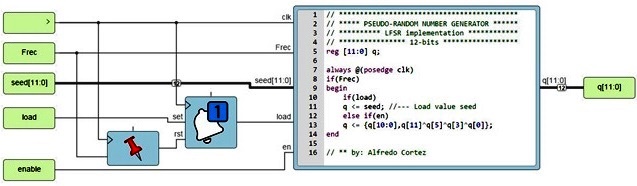
Fig. 1 Implementation of the 12-bit LFSR counter described in Verilog language under the Icestudio environment.
clk: This is the internal clock signal that controls the FPGA. On the Alhambra II board, it is set to 12 MHz.
Frec: This parameter configures the speed of the generated random sequence, also known as the sampling period of the LFSR.
seed [11:0]: This value, ranging from 0 to 4095, is input by the user to load the initial value or seed of the LFSR.
load: This pulse is received along with the value "seed [11:0]" to load the seed value.
enable: This input allows turning the LFSR counter on or off.
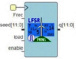
Figure 2 presents the block diagram of the 12-bit LFSR counter generated in Icestudio.
Since LFSR counters produce a sequence of uniformly distributed samples, a conversion technique is necessary to transform the samples into a routine or Gaussian distribution. To achieve this, the central limit theorem was applied, which states that the average value of random variables with a specific distribution converges to new random variables with a Gaussian distribution. For the Gaussian distribution generator block, four LFSR counter blocks were used, as shown in Figure 3. These blocks take the results of their random samples to a block responsible for calculating the average value in each produced sequence. First, the sum of the four samples is calculated, and then the result is right-shifted by 2 bits to obtain the division by 4.
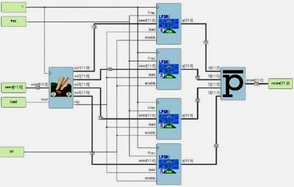
Fig. 3 Implementation of the block for generating random sequences with Gaussian distribution described in Verilog language under the Icestudio environment.
The operation for calculating the average value performed by the block is as follows:
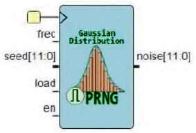
To the left of the four LFSR blocks, there is a seed value loading block responsible for assigning a different seed value to each LFSR counter. When the user sends a seed value, this block receives it and loads it into an internal LFSR counter that generates random sequences at the system speed, i.e., 12 MHz. Every 64 clock periods, a new random seed value is sent to each LFSR counter block. It is essential to highlight the purpose of this block since assigning the same seed value to each counter would result in the average value being equal to the produced value of the random sequence. In other words, the random number generator would retain the same uniform distribution, and applying the central limit theorem with the average value would have no effect. Figure 4 displays the block for generating random sequences with Gaussian distribution generated in Icestudio.
B. Noise signal generator.
As an immediate application of the designed block, it was used to create the noise-generating equipment. For this purpose, the block diagram shown in Figure 5 was proposed. Its implementation was carried out using the Alhambra II board, which, in addition to containing the free Lattice iCE40XH4K FPGA, includes an FTDI FT2232H IC for serial communication. This IC is required to convert the data sent serially via USB into a TTL signal that the FPGA can understand in UART communication. The FTDI block receives the generator's adjustment parameters sent by the user from a computer in serial form and delivers them to the FPGA. The user-sent adjustment parameters include the voltage, frequency, and seed value for generating random sequences. A 12-bit digital-to-analog converter (DAC) will take samples from the random sequences and convert them into an analog signal, then pass through the bipolar configuration stage for noise signal adjustment. This stage receives the "Vref" parameter from a 4-bit DAC for amplitude adjustment. Finally, the generated noise will reach a mixing network to contaminate signals additively.

The construction of this design under the Icestudio environment can be seen in Figure 6. The Icestudio tool library includes a block created by the open-source community that allows the reception of data sent in serial form. In this project, that block was used to receive the sent parameters, and a separate block was designed to organize and load the voltage, frequency, and seed value parameters into the Gaussian random sequence generator block. In Figure 6, it can be observed that the pins "DD3, DD2, DD1, DD0" were designated as outputs for adjusting the amplitude of the noise signal in conjunction with an externally connected 4-bit DAC. The pins "D0...D11" were selected for the digital output of the noise signal.
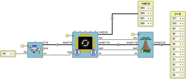
Fig. 6 Design of the noise generator under the Icestudio environment, indicating the “RX” serial reception input port and the output ports of the Alhambra II board.
Figure 7 shows the implementation of the block for organizing and loading the voltage, frequency, and seed value parameters under the Icestudio environment.
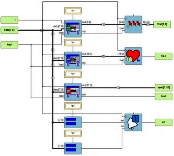
Fig. 7 Implementation of the block to organize and load the parameters of voltage, frequency, and seed value under the Icestudio environment .
Table I displays the resources consumed in the FPGA for the implemented Gaussian random sample generator design.
Table 1 Results of the resources used in the FPGA ICE40XH4K.
| ffs | LUTs | IOPs | PLBs | brams |
|---|---|---|---|---|
| 247 / 7680 | 2975 / 7680 | 22 / 107 | 550 / 960 | 0 / 32 |
The DAC7541 integrated circuit was used as a DAC converter, allowing a 12-bit input resolution for converting the random samples to analog signals. To control the amplitude of the noise signal, a 4-bit DAC converter was implemented using the R-2R resistor ladder network in voltage-summing mode.
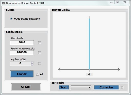
Under the Visual Studio 2019 environment, a GUI was developed to manipulate and interact with each of the parameters required by the noise generator. It consists of a program window organized into four divisions for control organization, as shown in Figure 8. The NOISE area displays the name of the generated noise, in this case, Gaussian white noise. The DISTRIBUTION area allows users to observe the distribution variation adjusted by interacting with the amplitude parameter. The PARAMETERS area contains forms that allow for manipulating the noise parameter data. And in the CONNECTION area, some controls enable establishing a connection with the board.
IV. RESULTS
A. Simulation of the Gaussian Random Sequence Generator Block
The design of the Gaussian random sequence generator block, developed in Icestudio, was verified by conducting a simulation in Apio IDE with its test bench. The data obtained from the simulation was exported and plotted in Matlab for better visualization. This result was compared with those obtained from a Gaussian random number generator designed in Matlab, with the same characteristics as the one implemented in Icestudio. As shown in Figure 9, the distribution obtained from the testbench samples closely approximates the result from the Matlab script design.
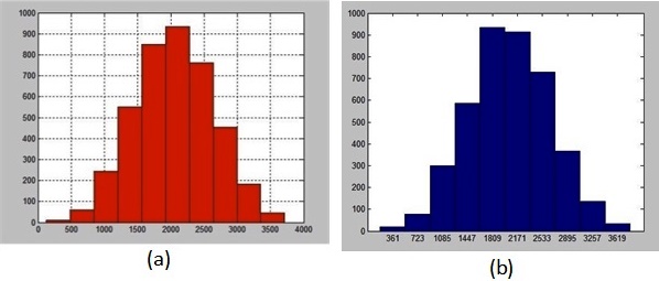
Fig. 9 (a) Histogram of the data obtained in the Celery IDE simulator and exported to Matlab to observe its distribution. (b) Histogram of the Gaussian distribution of the generator samples described in Matlab.
B. Noise Generator Testing
For these tests, square wave and sine wave signals provided by a function generator were used.
With Square Wave Signal: Noise was added to a square wave signal with an amplitude of 2.04 Vpp and a frequency of 1 kHz. The result can be seen in Figure 10, where (a) represents the signal without noise, (b) represents the signal with 0.412V of noise, and (c) represents the signal with 0.825V of noise.
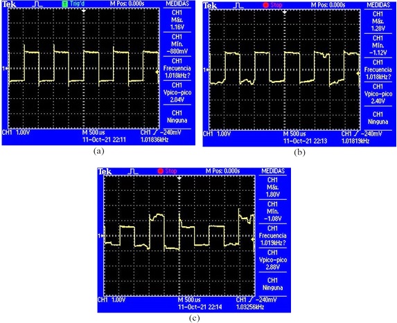
Fig. 10 Square Wave Signal: (a) No Noise, (b) Signal with 0.412V Amplitude Noise, and (c) Signal with 0.825V Amplitude Noise.
With Sinusoidal Signal: Noise was added to a Sinusoidal Signal with an amplitude of 1.88Vpp and a frequency of 1kHz. The result can be seen in Figure 11, where (a) represents the signal without noise, and (b) and (c) represent the signal with noise at 10kHz and 100kHz, respectively.
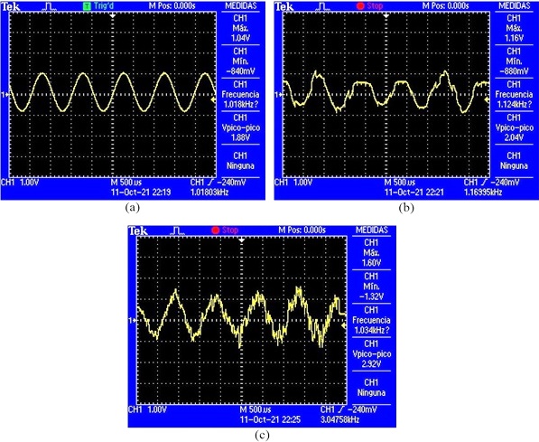
Fig. 11 Square Wave Signal: (a) No Noise, (b) Signal with 0.412V Amplitude Noise, and (c) Signal with 0.825V Amplitude Noise.
In the experiments conducted by contaminating external signals with noise, the effect on the signal was noticeable as the noise amplitude increased. The distortion effect caused by high-frequency noise on a signal was also observed.
To analyze the frequency spectrum of the generated noise, the Fast Fourier Transform (FFT) was used. Tests were conducted at different noise frequencies. Firstly, a test was performed at 100 kHz with the noise amplitude set to 1.03V. The spectral density of the noise for this case can be seen in Figure 12 (a) . Secondly, a test was conducted at a frequency of 50 kHz, with the noise amplitude also set to 1.03V. The spectral density of the noise for this case can be seen in Figure 12 (b) .
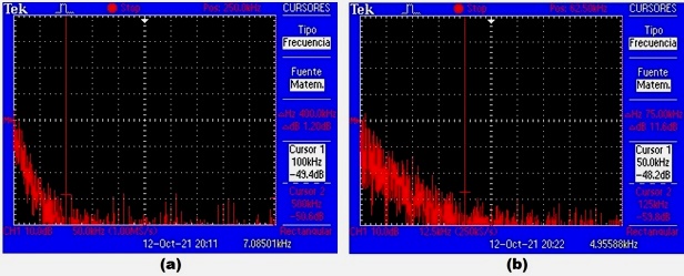
Fig. 12 (a) Frequency spectrum of the noise signal at 100 kHz. (b) Frequency spectrum of the noise signal at 50 kHz.
In this experiment, it was observed that at frequencies higher than the configured frequency in the equipment, the power density of the spectrum decreases as the frequency range increases. Furthermore, it was observed that the power density of the noise is contained in frequencies lower than the configured frequency, indicating that the noise is band-limited.
CONCLUSIONS
All the available open-source software for hardware development is beneficial for those who cannot afford licensed software. Icestudio offers not only economic advantages but also ease of use due to its capabilities and tools for developing any digital electronic circuit on a free FPGA. The Icestudio platform proves to be a good option for graphically describing hardware to be implemented in an FPGA. It provides the flexibility to create necessary blocks for different purposes using free FPGA communities or code blocks described in the Hardware Description Language (HDL) Verilog.
The Alhambra II development system can be used to study free FPGAs. Random samples with Gaussian distribution were successfully generated and implemented using the Hardware Description Language (HDL) Verilog. The necessary blocks were also designed to control and receive parameters sent from a graphical interface on a PC to the noise generator equipment.
In the experimental results, square and sine wave signals from a signal generator were contaminated, demonstrating the effect and distortion of the implemented equipment's noise on these signals.

